The Architecture of Subterranean Dryness: A Definitive Guide to Foundation Protection
Foundation waterproofing plans the structural integrity of any permanent edifice is inextricably linked to its relationship with the surrounding soil and the water contained therein. While the aesthetic and functional aspects of a building exist above the grade line, the longevity of the asset is determined in the dark, high-pressure environment of the foundation. Moisture is not merely a nuisance; it is a relentless solvent that facilitates the oxidation of reinforcement steel, the spalling of concrete, and the proliferation of biological contaminants.
As urban density increases and developments expand into geologically complex terrains, the demands placed on waterproofing systems have escalated. We are no longer in an era where a simple coat of tar suffices for subterranean defense. Modern building science requires a sophisticated understanding of hydrostatic pressure, soil porosity, and the chemical interactions between groundwater and building materials. To achieve a dry interior, an architect or property owner must navigate a complex landscape of membranes, drainage planes, and mechanical evacuation systems, each with specific failure modes and performance thresholds.
A comprehensive approach to subterranean protection requires a pivot from reactive repair to proactive asset management. This involves a rigorous assessment of the building’s “hydrologic footprint”—the way water moves across the site, sits against the walls, and rises from the water table. This article serves as an analytical reference for the strategies and technical considerations essential to achieving long-term subterranean stability.
Foundation Waterproofing Plans
When we analyze foundation waterproofing plans, we are essentially examining a multi-layered strategy designed to decouple a structure from its hydrologic environment. A common error in the industry is the conflation of “damp-proofing” with “waterproofing.” Damp-proofing is a retardant, intended only to slow the transmission of water vapor in well-drained soils. A definitive plan must address both the liquid and vapor phases of water to be successful over a fifty-year horizon.
The development of these plans requires a multi-perspective understanding of the site. From a civil engineering standpoint, the focus is on grading and the redirection of surface water. From a metallurgical and chemical perspective, the focus is on the membrane’s resistance to soil-borne sulfates and its ability to bridge structural cracks as the building settles. Oversimplification—such as relying solely on an interior sump pump without addressing exterior infiltration—often leads to “systemic fatigue,” where the mechanical components eventually fail under the sheer volume of incoming water.
Rigorous foundation waterproofing plans incorporate redundancy. This “defense-in-depth” approach assumes that any single component—be it a sheet membrane or a perforated drain pipe—might face a localized failure. The goal is the absolute elimination of moisture-driven entropy within the building’s footprint.
Contextual Background: The Evolution of Below-Grade Defense
Foundation waterproofing plans historically, foundation protection relied on the sheer mass of the materials. This worked for utilitarian storage but failed as the 20th century demanded finished, conditioned basements. The mid-century shift to concrete masonry units (CMU) and poured concrete introduced rigidity, which in turn introduced the problem of cracking. Early solutions often involved coal-tar pitch, which was effective but brittle and prone to chemical breakdown over time.
The late 20th century saw a revolution in polymer science, leading to the development of rubberized asphalt, HDPE (High-Density Polyethylene), and crystalline admixtures. We have moved from an era of “blocking” water to an era of “redirection,” acknowledging that it is far more effective to provide water with a path of least resistance away from the building than to try and stop it through force alone.
Conceptual Frameworks and Mental Models Foundation Waterproofing Plans
To evaluate the efficacy of a subterranean plan, one should employ these three frameworks:
-
The Hydrostatic Head Model: This model treats the foundation wall as a dam. The taller the column of water in the saturated soil outside, the higher the pressure at the base. The plan’s objective is to “lower the head” by moving water into a drainage system faster than the soil can resaturate.
-
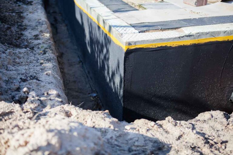
The Continuous Envelope Concept: Water acts as a precision seeker of weakness. If a membrane covers 99% of a wall but fails at the “cove joint” (where the wall meets the footing), the system is effectively compromised. Success is defined by the continuity of the barrier across all transitions and utility penetrations.
-
The Capillary Break Theory: Concrete is a capillary-active material; it can pull water upward from the footing against the force of gravity. A sophisticated plan includes a “capillary break”—a physical or chemical barrier between the footing and the wall—to stop this upward migration.
Categories of Waterproofing and Material Variations
Selecting a methodology requires a trade-off analysis between site constraints, soil chemistry, and capital expenditure.
Decision Logic for Implementation
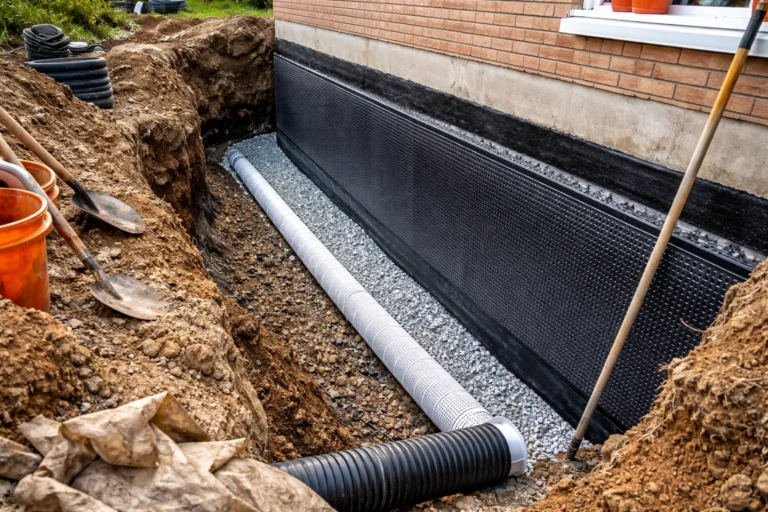
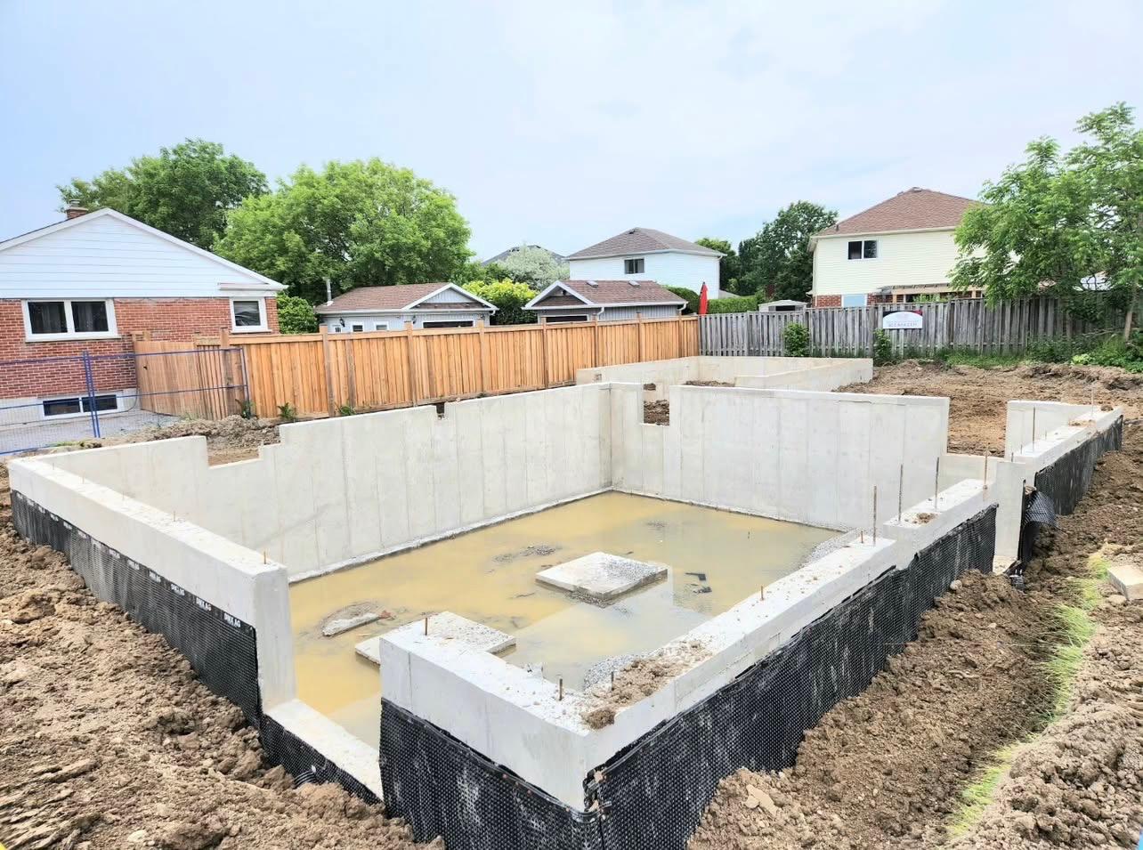
In high-clay soils where water lingers, the decision logic dictates a “Hybrid System”: a fluid-applied membrane for a seamless seal, protected by a dimpled drainage board to provide an air gap and a path to the weeping tile.
Detailed Real-World Scenarios Foundation Waterproofing Plans
Scenario A: The High-Water Table Coastal Build A structure built near a tidal zone faces a perpetually saturated foundation.
-
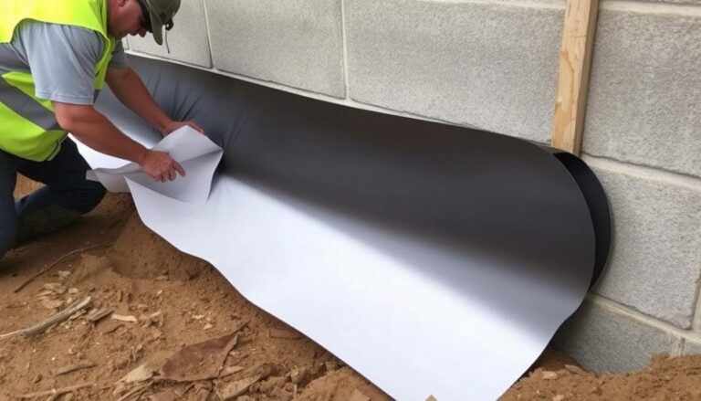
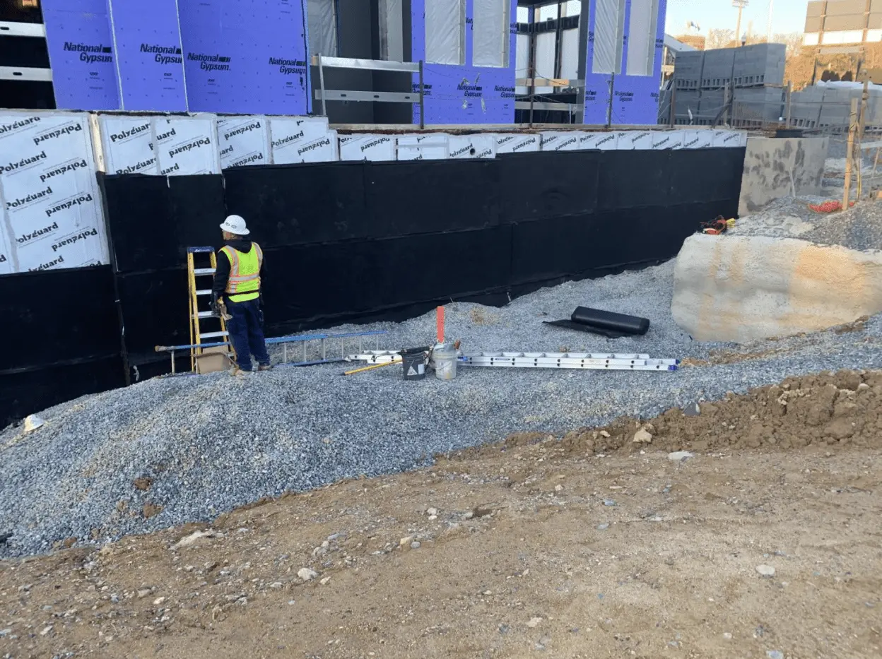
Plan: A “blind-side” waterproofing approach using a thick HDPE sheet membrane that is pinned to the shoring before the concrete is poured. The concrete bonds mechanically to the membrane, preventing water from traveling between the wall and the barrier.
Scenario B: The Urban Retrofit An existing building with a fieldstone foundation is experiencing seepage. Exterior excavation is impossible due to proximity to other buildings.
-
Plan: An internal “water management” system. A drainage track is installed at the base of the interior wall, covered by a vapor-retardant wall liner that directs seepage into a sump pit, bypassing the stone’s porosity.
Scenario C: The High-Sulfate Industrial Site Groundwater contains high levels of chemicals that degrade standard asphalt.
-
Plan: A specialized polyurethane-based fluid-applied membrane that offers high chemical resistance, paired with a crystalline admixture in the concrete pour for internal redundancy.
Economic Dynamics: Costs, Resources, and Lifecycle Value
Waterproofing is a “front-loaded” expense. The cost of installing a robust system during initial construction is a fraction of the cost of a retrofit.
Opportunity Cost: Choosing to save $5,000 on a new build by opting for damp-proofing can result in a $40,000 remediation bill if the basement is later finished and then floods. The loss of use and the impact on resale value further compound this deficit.
Strategic Tools and Integrated Support Systems
-
Waterstops: Specialized strips placed in the “cold joint” of the concrete pour to prevent water from traveling through the seam.
-
Termination Bars: Aluminum strips that mechanically fasten the top of a membrane to prevent it from sagging over time.
-
Hydrostatic Pressure Relief Valves: Floor-mounted valves that allow groundwater in only when pressure becomes dangerous, preventing floor buckle.
-
Battery-Backup Sump Systems: Ensuring mechanical evacuation continues during the power outages that often accompany storms.
-
Geotextile Filter Fabric: Essential for wrapping drainage gravel to prevent silt from clogging the system.
-
Laser Grading: Ensuring the soil slopes away from the foundation at a minimum 5% grade for at least 10 feet.
Risk Landscape and Failure Modes Foundation Waterproofing Plans
The primary risk in subterranean defense is the “Human Element.” Even the most advanced foundation waterproofing plans fail if the application is rushed.
-
Mechanical Puncture: Sharp rocks in the backfill can pierce a membrane if a protection board isn’t used.
-
Adhesion Failure: Applying a liquid membrane to wet or dusty concrete prevents a chemical bond, leading to “blistering.”
-
Systemic Clogging: Without filter fabric, the fine particles in the soil will eventually fill the voids in the gravel and the holes in the drain pipe, rendering the drainage plane useless.
-
Compounding Risk: A failure in the gutter system dumps concentrated water at the foundation, exceeding the capacity of the drainage tile and creating a localized “pressure point.”
Governance, Maintenance, and Long-Term Adaptation
A foundation is a “set it and forget it” system only in theory. In practice, it requires ongoing governance:
-
Quarterly Sump Testing: Manually triggering the pump to ensure the float switch and motor are operational.
-
Annual Grade Audit: Checking for soil settlement near the house that could create “negative grade” and pool water.
-
Biannual Gutter Cleaning: Preventing the overflows that saturate the backfill zone.
-
Layered Checklist:
-
Check for “efflorescence” (white salt deposits) on interior walls.
-
Ensure window well drains are free of leaves.
-
Measurement, Tracking, and Evaluation Foundation Waterproofing Plans
-
Leading Indicators: Increasing humidity levels in the basement (measured with a hygrometer) often precede a visible leak.
-
Lagging Indicators: Standing water, mold growth on baseboards, or a sump pump that runs 24/7 without rain.
-
Qualitative Documentation: Maintain a log of sump pump cycles during heavy rains. An unexplained increase in cycle frequency may indicate a change in the local water table or a clogging drainage pipe.
-
Documentation Examples: Photo records of the foundation before backfilling, receipts for pump maintenance, and an annual “dryness certification” by the property manager.
Common Misconceptions and Oversimplifications
-
“New concrete is waterproof”: False. Concrete is a porous, capillary-active material that will wick water until it is saturated.
-
“Tar is enough”: Standard asphalt damp-proofing is not a waterproofing membrane; it lacks the thickness and elasticity to bridge cracks.
-
“I can waterproof from the inside”: You can manage water from the inside, but you can only waterproof (stop the water from entering the wall) from the outside.
-
“Gutter guards solve foundation issues”: They help, but they don’t address rising groundwater or hydrostatic pressure.
-
“Plastic vapor barriers are all you need”: A plastic sheet on the ground does not stop lateral pressure from the walls.
Synthesis and Final Editorial Judgment
The development of foundation waterproofing plans is ultimately an exercise in risk mitigation and material stewardship. There is no singular “miracle” product that can compensate for poor site planning or a failure to understand the physics of water. The most resilient structures are those that treat the foundation as a dynamic interface, employing a multi-layered defense that combines high-performance chemical barriers with robust mechanical drainage. By prioritizing continuity and redundancy, the subterranean footprint of a building can remain a secure, dry, and permanent foundation for the life above it. Intellectual honesty in this field means admitting that water is the ultimate solvent; our goal is not to fight it, but to move it.