Blog

  • The Silent Sentinel: Navigating the Subterranean Shift in Flood Mitigation

    The Silent Sentinel: Navigating the Subterranean Shift in Flood Mitigation

    Modern smart sump technology usa the management of groundwater in residential and commercial architecture is undergoing a transformation that mirrors the broader digitization of mechanical infrastructure. For decades, the sump pump was a blunt instrument—a cast-iron or thermoplastic motor triggered by a simple mechanical float, operating in total isolation from the homeowner. This legacy approach to flood prevention relied entirely on the hope that a catastrophic mechanical failure or power outage would not coincide with a significant weather event. As climate patterns shift toward more frequent, high-intensity precipitation, the margin for error in basement water management has narrowed significantly, necessitating a move toward more intelligent, predictive systems.

    The emergence of sophisticated flood mitigation represents more than just the addition of Wi-Fi to a motor. It is the integration of sensor arrays, cloud-based telemetry, and redundant power management systems into a cohesive defense mechanism. This evolution is particularly relevant in the United States, where diverse geological conditions—from the heavy clays of the Midwest to the high water tables of the Atlantic coast—demand varying levels of technical resilience. The shift from “reactive” pumping to “proactive” water management is not merely a luxury upgrade; it is a fundamental reconfiguration of how we protect property value and structural integrity.

    To understand the current landscape of home protection, one must move beyond the superficial specifications of horsepower and flow rates. We must examine how data-driven feedback loops now allow for real-time monitoring of pump health, cycle frequency, and environmental variables that were previously invisible to the property owner. This analytical deep dive explores the mechanics, economics, and systemic complexities of contemporary water management, establishing a framework for what constitutes a high-performance subterranean defense system in the current era.

    Understanding “modern smart sump technology usa”

    Defining modern smart sump technology usa requires a multi-perspective approach that distinguishes between “connected” devices and truly “intelligent” systems. A common misunderstanding is that any pump with an internet-connected alarm qualifies as smart. In reality, a truly modern system is characterized by its ability to perform self-diagnostics, manage dual-power sources intelligently, and provide granular data on the basin’s hydrology. It is a shift from a binary state (On/Off) to a variable state where the system understands its own performance curve and can predict its own failure before a flood occurs.

    Oversimplification risks in this sector are high. Marketing often focuses on “peace of mind” via smartphone notifications, but for the engineering-minded, the value lies in the reduction of “latent risk.” A standard pump has a single point of failure: the mechanical switch. Modern technology replaces or augments this with solid-state sensors that have no moving parts to seize. Furthermore, these systems address the “USA-specific” challenge of varied power grid reliability and local building codes, integrating with battery backups that use sophisticated charging algorithms rather than simple trickle chargers.

    To view these systems correctly, one must see them as a component of the “Internet of Things” (IoT) that serves a critical safety function. Unlike a smart thermostat, which manages comfort, a smart sump system manages catastrophic risk. Therefore, the “best” technology is not necessarily the one with the most features, but the one with the highest “Mean Time Between Failures” (MTBF) and the most robust communication protocol when those failures inevitably appear.

    Deep Contextual Background: The Historical Trajectory

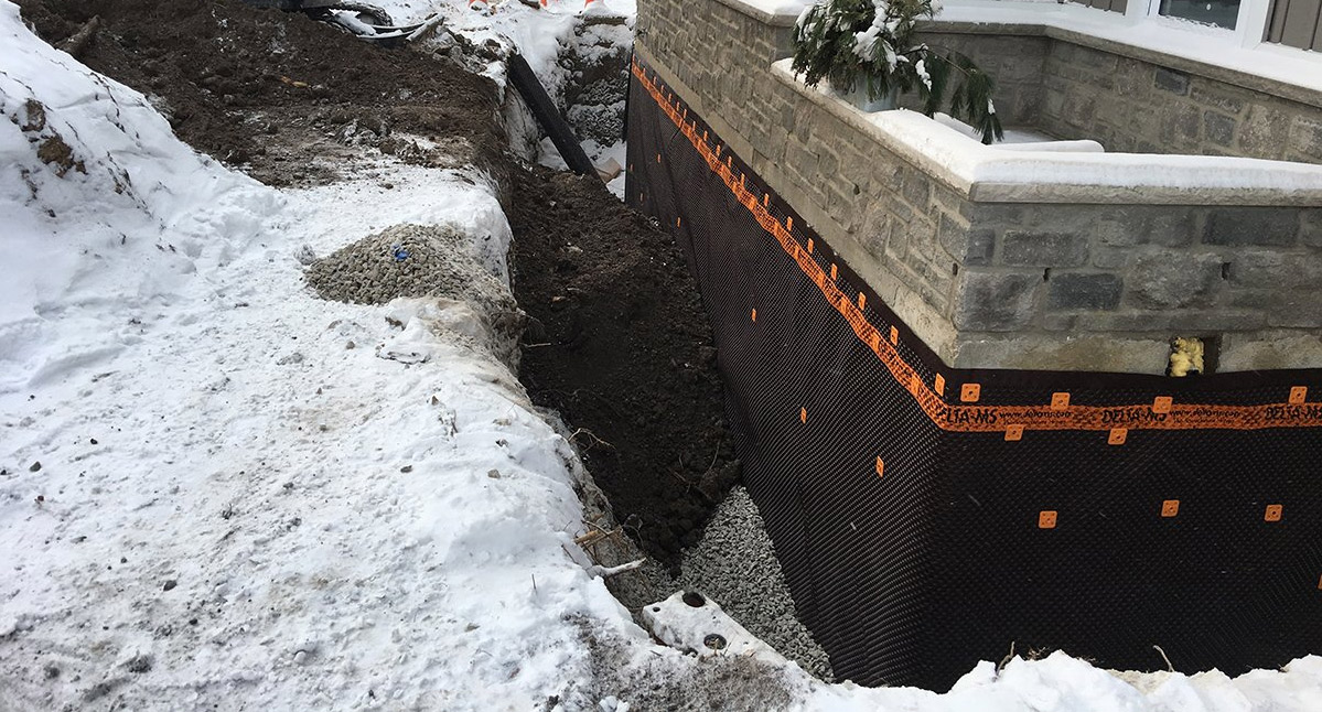
    Modern smart sump technology usa the history of the sump pump in the United States is a history of responding to urbanization. As more homes were built in floodplains and areas with high water tables, the necessity for mechanical drainage grew. The early 20th century relied on “pedestal” pumps, where the motor sat high above the pit, vulnerable to physical damage but easy to service. By the mid-century, submersible pumps became the standard, offering quieter operation and more efficient cooling by using the groundwater itself to dissipate motor heat.

    However, these systems remained “dumb.” They operated until they burned out, often during the very storms they were designed to mitigate. The 1990s introduced the first wave of battery backups, but these were rudimentary lead-acid systems that often failed because the batteries were not maintained. The current era of modern smart sump technology usa was birthed from the intersection of two trends: the miniaturization of sensors and the ubiquity of home Wi-Fi. We are now in a phase where “edge computing” is applied to the sump pit, allowing the system to distinguish between a routine cycle and an emergency inflow rate without needing to contact a central server.

    Conceptual Frameworks and Mental Models Modern Smart Sump Technology Usa

    To navigate the complexity of modern water management, we can utilize several mental models that frame the system’s role in the home.

    1. The Redundancy Hierarchy

    This framework suggests that a system is only as strong as its secondary and tertiary layers.

    • Layer 1: Primary AC Pump (High capacity).

    • Layer 2: Secondary DC Pump (Emergency backup).

    • Layer 3: Telemetry/Alerting (Information layer). The “smart” component lives in Layer 3 but manages the transition between Layers 1 and 2.

    2. The Hydrological Load Profile

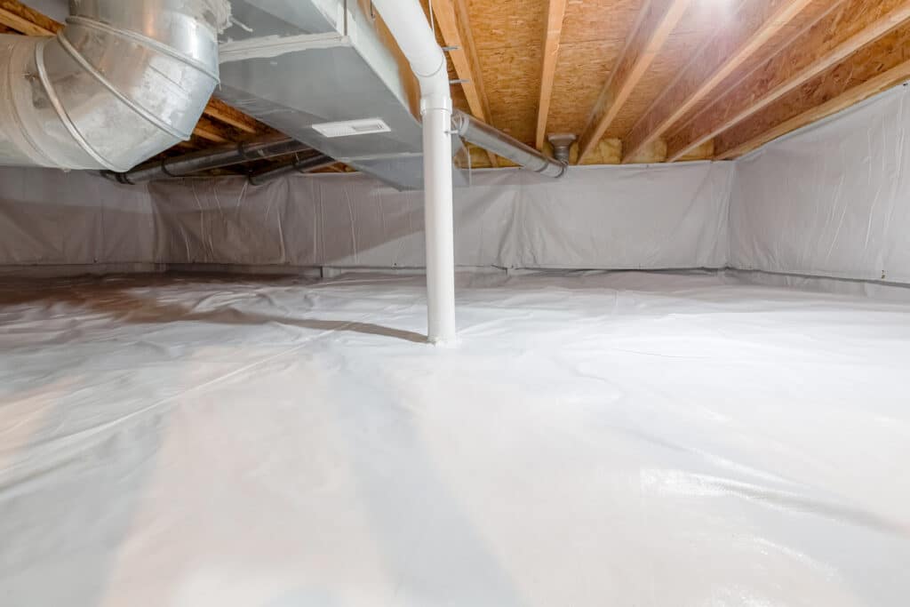
    Property owners should view their basement not as a static box, but as a dynamic participant in the local water table. A “smart” system tracks the “duty cycle”—how often the pump runs per hour. A mental model of the basement as a “leaky vessel” helps in understanding that the pump’s job is to maintain a specific equilibrium pressure against the foundation.

    3. The Failure Mode and Effects Analysis (FMEA)

    Professionals use this to identify what happens when a component fails. In a smart system, the FMEA is built into the software. If the primary pump’s current draw spikes (indicating a jam), the system doesn’t just wait for the water to rise; it proactively switches to the backup and alerts the user.

    Key Categories and Variations

    Not all smart systems are designed for the same architectural constraints. The following table outlines the primary variations in the U.S. market.

    Category Core Advantage Primary Trade-off Ideal Use Case
    Integrated Dual-Pump Systems Seamless handover between AC/DC. High initial capital expenditure. Finished basements with high-value assets.
    Retrofit Smart Controllers Adds intelligence to existing “dumb” pumps. Potential compatibility issues with some motors. Budget-conscious upgrades of reliable hardware.
    Cloud-Native Pumping Arrays Deep data analytics and remote testing. Requires stable, always-on internet. Managed properties or second homes.
    Solid-State Sensing Units No moving parts; eliminates float failure. More sensitive to turbulence in the pit. Pits with limited physical clearance.

    Realistic Decision Logic

    When selecting a system, the decision should follow a logic of “Consequence of Failure.” If a basement is unfinished and used for utility, a retrofit controller might suffice. If the space is a high-end living area with custom millwork, an integrated dual-pump system with satellite-linked telemetry represents the necessary standard of care.

    Detailed Real-World Scenarios Modern Smart Sump Technology Usa

    Scenario 1: The Multi-Day Power Outage (Northeastern Winter)

    A heavy ice storm knocks out power for 72 hours. Standard backups would deplete.

    • Modern Response: The system detects the outage and shifts to an “eco-mode,” pulsing the pump to conserve battery life based on the rate of water rise rather than a fixed float level.

    • Constraint: Battery chemistry (AGM vs. Lithium).

    Scenario 2: The “Silent” Primary Pump Failure

    A primary pump motor seizes during a dry spell. The homeowner is unaware until the next storm.

    • Modern Response: The smart controller performs a weekly “dry run” or low-level test. It detects the motor is drawing 0 amps and sends an alert weeks before the rain arrives.

    • Second-Order Effect: Prevention of emergency plumbing rates during a storm.

    Cost Dynamics and Resource Allocation

    Investing in modern smart sump technology usa involves both direct hardware costs and indirect lifecycle costs.

    Item Estimated Range (USD) Note on Variability
    Primary Smart Pump $400 – $900 Varies by GPH (Gallons Per Hour) and head pressure.
    Battery Backup Array $300 – $1,200 Lithium-ion batteries significantly increase cost.
    Professional Installation $500 – $1,500 Depends on pit modification and electrical work.
    Subscription Services $0 – $100/yr Some premium cloud features require a fee.

    Opportunity Cost: The cost of a “dumb” system plus one medium flood cleanup (average $10,000+) far outweighs the $2,500 investment in a top-tier smart array.

    Risk Landscape and Failure Modes Modern Smart Sump Technology Usa

    Even the most advanced systems are subject to the laws of physics and the limitations of digital infrastructure.

    • Network Latency and Outages: If the “smart” feature relies entirely on the cloud, a router failure during a storm renders the notification system useless. Localized alarms (audible) remain a critical fallback.

    • Sensor Fouling: In areas with high iron ochre or mineral deposits, solid-state sensors can become coated, leading to false readings.

    • The “Notification Fatigue” Risk: If a system sends too many non-critical alerts (e.g., “Power flicker detected”), the user may begin to ignore notifications, leading to a missed “Pump Failed” alert.

    Governance and Maintenance

    A smart system requires a different maintenance cadence than a mechanical one. It transitions from physical inspection to “digital governance.”

    Layered Maintenance Checklist:

    • Quarterly: Clear the pit of debris; verify the Wi-Fi signal strength at the controller.

    • Bi-Annually: Manually trigger the backup pump to ensure the battery can hold a load, not just a voltage.

    • Annually: Inspect the check valve for “water hammer” and wear; update the system firmware if applicable.

    Common Misconceptions Modern Smart Sump Technology Usa

    1. “Wi-Fi makes the pump better at pumping.” No, Wi-Fi makes the owner better at managing. The pump’s physical capacity remains a matter of horsepower and impeller design.

    2. “Smart pumps don’t need maintenance.” Incorrect. They require less manual testing, but they still require physical cleaning of the basin.

    3. “Battery backups last forever if not used.” Standard lead-acid batteries have a shelf life of 3-5 years regardless of use. Smart systems help track this age, but they don’t stop the chemical degradation.

    Conclusion: The Synthesis of Intelligence and Utility

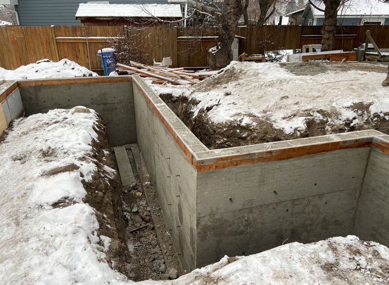
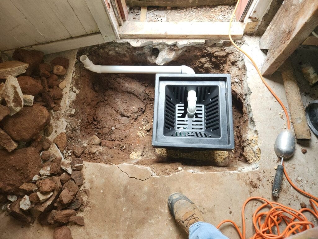
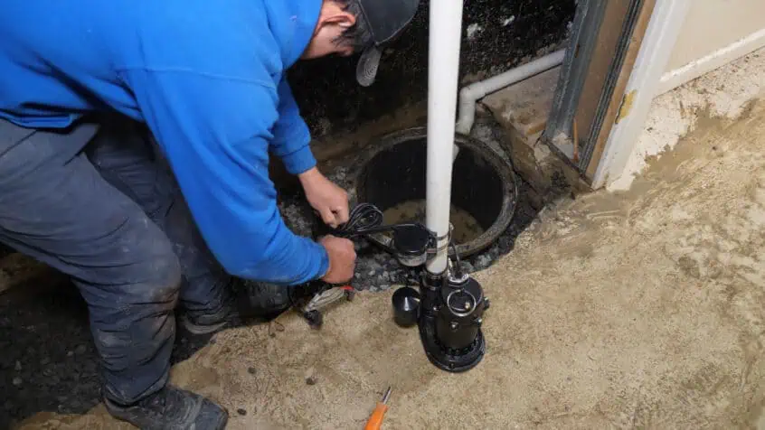
    The adoption of modern smart sump technology usa represents a shift toward a more sophisticated understanding of residential risk. By moving away from isolated, mechanical components and toward integrated, data-aware systems, property owners can significantly mitigate the unpredictability of groundwater. However, the technology is not a “magic bullet.” Its effectiveness remains rooted in proper physical installation—correctly sized basins, clear discharge lines, and robust check valves.

    The future of this field likely involves further integration with municipal “smart city” data, where a home’s sump system might adjust its behavior based on incoming hyper-local weather data or neighborhood-wide water table fluctuations. Until then, the most effective approach remains a combination of high-quality mechanical engineering and the proactive telemetry provided by modern digital controllers. Success in this domain is measured not by the complexity of the app, but by the dryness of the basement when the grid goes dark and the clouds open.

  • The Architectural and Economic Evolution of Subterranean Living Spaces

    The Architectural and Economic Evolution of Subterranean Living Spaces

    Best basement finishing in the us modern residential architecture in the United States has undergone a quiet but profound shift. Once relegated to utility—serving as damp storage for boilers, seasonal decor, and laundry—the basement has transitioned into a primary theater for home equity growth and lifestyle expansion. Defining the best basement finishing in the us requires moving past the superficial application of drywall and carpet. It demands an interrogation of building science, regional geological constraints, and the shifting socioeconomic value of square footage.

    The complexity of these projects stems from the fact that a basement is, essentially, a concrete vessel submerged in soil. It is an environment perpetually battling hydrostatic pressure, thermal bridging, and vapor transmission. Consequently, the pursuit of a high-tier finished basement is not merely a cosmetic endeavor but a sophisticated engineering task. Homeowners and developers now approach these spaces with the same rigor applied to primary living suites, integrating advanced HVAC zoning, acoustic engineering, and moisture-mitigation technologies that were once reserved for commercial infrastructure.

    This analysis explores the multifaceted nature of basement transformation across the diverse American landscape. From the frost-heave challenges of New England to the expansive clay soils of the Midwest and the seismic considerations of the West Coast, the definition of “best” shifts according to localized variables. To achieve topical mastery in this domain, one must look at the intersection of material science, regulatory compliance, and the long-term viability of the investment.

    Understanding “Best Basement Finishing in the US”

    The phrase best basement finishing in the us is often misinterpreted as a search for the most luxurious or expensive aesthetic. However, from an editorial and engineering perspective, “best” is a metric of resilience and integration. A basement that features Italian marble but lacks a redundant sump pump system with battery backup is, by professional standards, a failure. The highest tier of finishing is defined by how well the invisible systems—insulation, drainage, and air quality—support the visible finishes.

    Common misunderstandings often center on the idea that a basement is simply an “upstairs room, but downstairs.” This oversimplification ignores the physics of subterranean environments. In the U.S., regional building codes vary significantly, meaning that what constitutes a high-quality finish in Georgia (where crawlspaces are common) differs vastly from Minnesota (where deep foundations are standard). True mastery of this topic involves recognizing that a premium finish is one that manages the “stack effect” of the home, ensuring that the basement does not become a source of radon or mold that affects the upper floors.

    Furthermore, the “best” approach acknowledges the paradox of permanence. Because basements are prone to unforeseen water events—whether from plumbing failures above or ground seepage below—the most sophisticated designs utilize inorganic materials. Using wood studs and paper-faced drywall in a high-risk moisture zone is a fundamental error, regardless of how well the space is decorated. The modern gold standard involves magnesium oxide boards, metal framing, and closed-cell spray foam or rigid mineral wool insulation.

    The Historical and Systemic Evolution of the American Basement

    Best basement finishing in the us historically, the American basement was a “cellar,” a cold-storage area for perishables and coal. As central heating evolved, the cellar became the mechanical heart of the home. Post-WWII, the suburban housing boom introduced the “recreation room,” characterized by wood paneling and asbestos tile. This was the first era of basement finishing, though it was largely DIY and lacked moisture-proofing logic.

    In the 1980s and 90s, the “man cave” or “home theater” trend emerged, driving a demand for more professional finishes. However, these often failed within a decade because they relied on traditional “above-grade” building techniques. We are currently in the fourth generation of basement evolution: the Integrated Living Suite. This era is defined by seamlessness—where the basement is indistinguishable from the rest of the home in terms of ceiling height, lighting quality, and atmospheric comfort.

    Systemically, this shift has been supported by advancements in “basement systems” franchises and specialized waterproofing technologies. The industry has moved from “interior drainage” (managing water after it enters) to “holistic envelope management” (preventing entry and managing vapor).

    Conceptual Frameworks and Mental Models Best Basement Finishing In The Us

    To evaluate or execute the best basement finishing in the us, professionals use several mental models to navigate the complexity of the project.

    1. The “Boat Hull” Logic

    Think of the basement as a boat hull sitting in water. Every penetration (windows, pipes, cracks) is a potential leak point. This framework prioritizes the exterior seal and the mechanical expulsion of water over interior aesthetics. If the “hull” isn’t sound, the “cabin” (the finish) will eventually be ruined.

    2. The 2-10-25 Rule of Longevity

    • 2 Years: The timeframe in which poorly installed drywall or flooring will show signs of moisture stress.

    • 10 Years: The cycle for mechanical pump replacement and battery renewal.

    • 25 Years: The expected lifespan of a high-quality, inorganic finish before it requires a stylistic refresh.

    3. The Thermal Bridge Break

    In cold climates, the concrete wall acts as a thermal bridge, pulling heat out of the home. The mental model here is “Continuous Insulation.” Any gap in the insulation layer creates a dew point where condensation will form. A “best” finish eliminates these gaps entirely using rigid foam or spray foam directly against the masonry.

    Key Categories and Variations in Finish Levels

    Finishing styles and qualities are not monolithic. They range from functional utility to high-end bespoke environments.

    Category Primary Focus Material Choice Risk Profile
    Mechanical/Utility Storage & Laundry Poured epoxy floors, exposed ceilings Low
    Standard Recreational Playrooms, Gyms Traditional drywall, luxury vinyl plank (LVP) Medium
    Secondary Living In-law suites, Bedrooms Egress windows, full baths, fire-rated doors High (Regulatory)
    Technical/Specialized Recording studios, Wine cellars Acoustic decoupling, climate control High (Complexity)
    Luxury Integrated High-end bars, Spas Custom millwork, stone veneers, heated floors High (Cost)

    Realistic Decision Logic

    Choosing the “best” category depends on the Opportunity Cost of the Footprint. If the home is in a high-density urban area (like Boston or DC), a full legal bedroom (requiring an egress window) yields the highest ROI. If the home is a sprawling suburban estate, a specialized technical space (like a high-fidelity home cinema) might add more intrinsic value.

    Detailed Real-World Scenarios Best Basement Finishing In The Us

    Scenario 1: The High-Water Table Midwestern Basement

    In regions like Northern Illinois or Michigan, the water table can be incredibly high. A “best” finishing project here focuses on Redundancy.

    • Decision Point: Installing two sump pumps with independent circuits and a water-powered backup.

    • Failure Mode: Relying on a single pump during a power-outage-inducing thunderstorm.

    • Second-Order Effect: Lower insurance premiums and peace of mind during spring thaws.

    Scenario 2: The Urban Row-House Dig-Out

    In cities like Philadelphia or New York, finishing a basement often involves “underpinning” to increase ceiling height.

    • Constraint: Structural integrity of shared party walls.

    • Decision Point: Bench-footing vs. true underpinning.

    • Outcome: Creating a 9-foot ceiling in a space that was previously a 5-foot crawlspace.

    Cost Dynamics and Resource Allocation

    When pursuing the best basement finishing in the us, budget allocation often surprises homeowners. A common mistake is spending 70% of the budget on what is visible. The professional standard suggests a 50/50 split between “Infrastructure” (waterproofing, HVAC, electrical, insulation) and “Finishes” (flooring, cabinetry, lighting).

    Estimated Cost Ranges (Per Square Foot)

    Level Price Range (USD/sq ft) Key Cost Driver
    Basic Finish $40 – $70 Basic electrical and drywall
    Mid-Range $75 – $120 Bathroom addition and LVP flooring
    High-End/Bespoke $150 – $300+ Structural changes, custom bars, HVAC zoning

    Direct vs. Indirect Costs: A direct cost is the flooring. An indirect cost is the increase in property taxes due to added “habitable” square footage. Understanding these dynamics is essential for a sustainable investment.

    Tools, Strategies, and Support Systems

    Achieving a premier result requires specific strategies that transcend standard carpentry.

    1. Dehumidification (Built-in): Portable units are insufficient. The best finishes utilize whole-house dehumidifiers integrated into the HVAC, maintaining a constant 45% humidity.

    2. Acoustic Decoupling: Using resilient channels or “hat channels” on the ceiling to prevent footfall noise from the main floor from ruining the basement’s ambiance.

    3. Sub-Floor Systems: Dimpled plastic membranes (like DMX or Delta-FL) create an air gap between the cold concrete and the flooring, preventing mold and keeping the floor warm.

    4. Egress Technology: Beyond safety, modern egress windows use high-clarity glass and decorative wells to flood the basement with natural light, removing the “dungeon” feel.

    5. Smart Leak Detection: Wi-Fi-enabled sensors placed at every plumbing fixture and the sump pit to provide instant alerts to a smartphone.

    6. Low-VOC Materials: Because basements have less natural ventilation, using low-VOC paints and adhesives is critical for long-term respiratory health.

    Risk Landscape and Failure Modes Best Basement Finishing In The Us

    The “failure” of a basement finish is rarely a single event; it is a compounding series of oversights.

    • Capillary Rise: Water wicking up through the concrete floor into the base of wooden studs.

    • The “Fish Tank” Effect: Waterproofing the walls so well that if a pipe bursts inside, the water cannot escape, effectively filling the basement like a tank.

    • Radon Accumulation: Finishing a basement can seal the floor but trap radon gas if a mitigation system wasn’t installed first. This is a significant health risk in many parts of the U.S.

    • Permit Avoidance: Finishes done without permits may need to be torn out upon home sale, or worse, lead to denied insurance claims after a fire or flood.

    Governance, Maintenance, and Long-Term Adaptation

    A finished basement is not a “set it and forget it” project. It requires an ongoing governance cycle.

    Annual Maintenance Checklist:

    • Spring: Test sump pumps; check exterior gutters and downspouts (ensure they discharge 10+ feet from the foundation).

    • Summer: Monitor humidity levels; inspect AC condensate lines.

    • Fall: Check for foundation cracks; service the furnace/boiler located in the mechanical room.

    • Winter: Monitor for “ice damming” that might cause seepage behind the foundation top.

    Adjustment Triggers: If the basement smells “musty,” the governance has failed. This is an immediate trigger to inspect the vapor barrier or dehumidification system.

    Measurement, Tracking, and Evaluation Best Basement Finishing In The Us

    How do you measure if you have the best basement finishing in the us?

    Qualitative Signals:

    • The space feels as warm and dry as the second floor.

    • There is no “basement smell.”

    • The transition from the stairs feels natural, not like entering a separate zone.

    Quantitative Indicators:

    • Relative Humidity: Consistently between 40% and 50%.

    • Radon Levels: Below 4.0 pCi/L (the EPA action level).

    • Appraisal Value: A recovery of 65% to 75% of the project cost in home equity.

    Common Misconceptions and Oversimplifications

    1. “My basement has been dry for 20 years, I don’t need waterproofing.” Past performance does not guarantee future results. Grading changes or neighborhood construction can shift water tables instantly.

    2. “Carpet makes the basement feel warmer.” Carpet acts as a filter for dust and a breeding ground for mold if there is any vapor transmission. Hard surfaces with area rugs are superior.

    3. “I can just use ‘waterproof’ paint on the walls.” Hydrostatic pressure will eventually peel any paint. Real waterproofing happens on the exterior or through a managed interior drainage system.

    4. “Recessed lights are all I need.” Basements require layered lighting—ambient, task, and accent—to overcome the lack of natural sun.

    Conclusion: The Synthesis of Art and Engineering

    The best basement finishing in the us is a symphony of moisture management, thermal comfort, and architectural integration. It is an exercise in intellectual honesty—admitting that the environment is hostile and building accordingly. When done correctly, it does not just add “extra space”; it transforms the very character of the home, providing a sanctuary that is as durable as it is beautiful. The measure of success is not found in the first year of occupancy, but in the tenth, when the space remains as pristine, dry, and healthy as the day the last coat of paint dried. Success requires a commitment to the invisible, ensuring that the foundation of the finish is as solid as the foundation of the house itself.

  • The Impermeable Aesthetic: A Technical Inquiry into High-Performance Interior Surfaces

    The Impermeable Aesthetic: A Technical Inquiry into High-Performance Interior Surfaces

    Luxury waterproof flooring usa the historical tension between architectural beauty and utilitarian resilience has found a modern resolution in the evolution of specialized interior surfaces. For decades, the pursuit of “luxury” in American flooring was synonymous with porous, vulnerable materials—solid hardwoods that bowed at the sight of a spill or natural stones that etched under the slightest chemical imbalance. As the domestic landscape shifts toward open-plan living and multi-generational households, the demand has pivoted. The contemporary objective is a surface that offers the haptic and visual depth of traditional materials while maintaining a total metabolic indifference to moisture.

    This shift has necessitated a radical re-engineering of the floor’s core. We are no longer discussing simple “water-resistant” coatings that provide a few hours of protection before the substrate swells. The current benchmark involves a fundamental change in material science, utilizing Stone Plastic Composite (SPC) and Wood Plastic Composite (WPC) to create a dimensionally stable plank that remains inert when submerged. In the American market, this transition is not merely about surviving floods or plumbing failures; it is about the “lifestyle of convenience”—the ability to maintain a high-design aesthetic in bathrooms, kitchens, and mudrooms without the fear of structural entropy.

    To specify a floor in the high-end residential or commercial sector requires more than a visual selection. It demands an analytical understanding of the “wear layer” thickness, the density of the mineral core, and the acoustic properties of the integrated underlayment. A failure to distinguish between a commodity-grade product and a professional-grade installation can lead to telegraphing, joint failure, and off-gassing issues that compromise the long-term value of the asset. This inquiry serves as a definitive reference for those seeking to bridge the gap between high-level interior design and the physics of moisture management.

    Understanding “Luxury Waterproof Flooring USA”

    Defining luxury waterproof flooring usa requires a multi-perspective analysis that looks past the surface-level grain patterns. From a material science perspective, “luxury” in this context refers to the depth of the decorative film and the realism of the “Embossed in Register” (EIR) texture, which aligns the physical grain of the plank with the visual image. In the American domestic market, a product only achieves luxury status when it can convincingly replicate the “hand-scraped” or “wire-brushed” finish of authentic timber while remaining completely impervious to the humidity fluctuations common in coastal or tropical climates.

    A common misunderstanding among stakeholders is the conflation of “waterproof” with “floodproof.” While the planks themselves are often made of inert minerals and polymers that will not swell, the installation system—typically a click-lock floating floor—is not a vapor-tight seal. If a significant volume of water remains on the surface for a prolonged period, it can seep through the perimeter or the joints, trapping moisture between the flooring and the subfloor. This creates a “micro-climate” conducive to mold growth. Therefore, a luxury standard is as much about the perimeter sealing and the subfloor preparation as it is about the material itself.

    Oversimplification risks are particularly high when discussing “wear layers.” Many consumers assume that a thicker wear layer automatically equates to a better product. However, the chemistry of the wear layer—specifically the inclusion of ceramic bead technology or aluminum oxide—is what dictates the scratch resistance and the “sheen levels” over time. A 20-mil wear layer of inferior polymer will underperform a 12-mil layer reinforced with mineral particles. Mastery in this sector involves balancing the “Hardness” (Shore D rating) of the core with the “Flexibility” of the locking mechanism to ensure the floor doesn’t become brittle in the sub-zero winters of the American North.

    Contextual Background: The Evolution of Resilient Surfaces

    Luxury waterproof flooring usa the American journey toward waterproof surfaces began with linoleum and vinyl “sheet” flooring in the mid-20th century. These were utilitarian choices, relegated to service areas and secondary rooms. They offered moisture protection but lacked the architectural “weight” required for primary living spaces. The 1990s introduced laminate—a high-density fiberboard (HDF) product that looked like wood but acted like cardboard when exposed to moisture. The catastrophic failure of early laminate in wet areas created a “trust gap” in the market that lasted for a generation.

    The introduction of Luxury Vinyl Tile (LVT) and its successors, WPC and SPC, fundamentally altered the trajectory. Manufacturers realized that by replacing the HDF core with a mixture of limestone powder and polyvinyl chloride (PVC), they could create a plank that was dimensionally stable and 100% waterproof. This innovation allowed “wood looks” to migrate into the bathroom for the first time without the risk of rot. Today, we are seeing the rise of “Mineral Core” flooring—an ultra-dense, PVC-free alternative that represents the next iteration of the luxury standard, focusing on environmental sustainability and fire resistance.

    Conceptual Frameworks and Mental Models Luxury Waterproof Flooring Usa

    Navigating the specification of high-performance floors requires specific mental models:

    • The “Telegraphing” Framework: Viewing the floor as a thin skin. Any imperfection in the subfloor (a nail head, a dip, or a crack) will eventually “telegraph” or show through the surface of the floor due to the pressure of foot traffic.

    • The “Joint Integrity” Logic: Understanding that the locking mechanism is the weakest point. The floor is only as waterproof as the “tightness” of the click-lock system. If the subfloor isn’t level, the joints will “flex” and eventually break, compromising the seal.

    • The “Thermal Expansion” Mental Model: Even though the material is waterproof, it is still subject to thermal physics. Planks will expand and contract as the sun hits them. A “luxury” installation must include the correct “expansion gaps” at the perimeter to prevent buckling.

    Key Categories of Waterproof Variations and Trade-offs

    Choosing the right substrate core is a balance of comfort, durability, and site conditions.

    Decision Logic: The “Drop-Test” Calculus

    If the project is a high-traffic commercial lobby with heavy furniture, the logic mandates SPC for its compressive strength. If the project is a residential bedroom or nursery, the logic shifts to WPC for its superior “foot-feel” and sound-dampening properties.

    Detailed Real-World Scenarios and Decision Logic

    Scenario A: The Modern Kitchen Renovation

    A family wants a seamless floor from the dining room into the kitchen. The logic: The kitchen is a “wet zone” with high “impact risk” (dropped pots). A standard wood floor would stain and dent. The strategy requires a high-end SPC with a 22-mil wear layer. This provides the necessary hardness for the kitchen while maintaining the visual continuity of the dining area.

    Scenario B: The Coastal Beach House

    A property in a high-humidity environment (Florida or the Carolinas). The logic: Traditional wood will expand and “cup” due to ambient moisture. The strategy involves a WPC floor with a cork underlayment. The WPC is inert to the humidity, and the cork provides a natural resistance to mold and mildew while offering a “soft” feel for bare feet.

    Planning, Cost, and Resource Dynamics Luxury Waterproof Flooring Usa

    The economics of luxury waterproof flooring usa are defined by the “Prep-to-Material” ratio. In many high-end installs, the cost of leveling the subfloor equals or exceeds the cost of the material.

    • Direct Costs: Luxury planks range from $5.00 to $12.00 per square foot. High-performance underlayments and transition moldings add another $1.00–$2.50.

    • Indirect Costs: Self-leveling compounds, moisture barriers (for concrete slabs), and the labor of removing existing baseboards to maintain the expansion gap.

    • Opportunity Cost: Choosing a “cheap” waterproof floor. If the locking system fails in three years, you lose the material cost AND the labor cost of the second installation.

    Tools, Strategies, and Support Systems

    A definitive installation requires a specific “Resilient” toolkit:

    1. Tapping Block and Pull Bar: Essential to engage the locking system without damaging the fragile “tongue” of the plank.

    2. 6-Foot Straightedge: To verify subfloor flatness (typically 3/16″ over 10 feet).

    3. Non-Silicone Perimeter Sealant: Used in bathrooms to seal the expansion gap between the floor and the tub/shower.

    4. Acoustic Underlayment (IXPE/Cork): To meet “IIC” (Impact Insulation Class) ratings in multi-story condos.

    5. PH Test Kits: For concrete slabs; high alkalinity can degrade the adhesives or the underlayment over time.

    6. Guillotine Cutters: To make clean, dust-free cuts inside the house without the “burrs” associated with saws.

    7. Transition Moldings (Flush-mount): The hallmark of luxury; avoid the “bulky” T-molds used in low-end installs.

    Risk Landscape and Failure Modes Luxury Waterproof Flooring Usa

    The primary failures in waterproof flooring are rarely about the water; they are about the “Systemic Environment.”

    • The “Floating Floor Pinch”: If heavy kitchen islands are built on top of the flooring, it cannot expand. This leads to joint separation or buckling in other parts of the room.

    • The “Subfloor Moisture Trap”: On concrete slabs, even though the floor is waterproof, the slab can “sweat.” Without a 6-mil poly vapor barrier, this moisture stays trapped and creates a mold-laden slurry under the floor.

    • Sun-Loading Warpage: Extreme direct sunlight through large windows can heat SPC to over 160°F, causing “cupping” if the material isn’t high-density or if the expansion gaps are insufficient.

    Governance, Maintenance, and Long-Term Adaptation

    Maintaining the “Luxury” aesthetic is a matter of “Non-Abrasive” stewardship:

    • Quarterly Joint Audits: Checking for “gaps” near heavy furniture or high-traffic doorways. If gaps appear, it indicates the floor is “shifting” and may need a friction-tape adjustment.

    • The “Neutral pH” Cleaning Rule: Never use steam mops (which can force moisture into the joints) or wax-based cleaners. A neutral pH cleaner ensures the wear layer doesn’t become cloudy.

    • Protection Cycles: Replacing felt pads on furniture every 12 months. Grit trapped in an old felt pad is the leading cause of wear-layer scratching.

    • Adjustment Triggers: If a plank is damaged, luxury systems allow for “individual plank replacement” using a specialized plunge-cut technique, avoiding a full-room teardown.

    Measurement, Tracking, and Evaluation Luxury Waterproof Flooring Usa

    Evaluation is based on “Visual and Acoustic Stability”:

    1. Quantitative: The “Levelness” Metric. Re-measuring the floor after 12 months to ensure no “dipping” has occurred as the house settled.

    2. Qualitative: The “Hollow-Sound” Test. Walking the floor to listen for “clacking” or “hollow” spots, which indicate a failure of the underlayment or subfloor prep.

    3. Leading Indicators: Relative humidity tracking in the home. A floor that stays stable between 30% and 50% RH will have a 50% longer joint life.

    4. Documentation: Maintaining a “Batch Record”—saving the box ends from the installation so that if a repair is needed years later, the “color run” can be matched exactly.

    Common Misconceptions and Industry Myths

    • Myth: “You can put waterproof flooring over carpet.” Reality: Never. The “squish” of the carpet will break the locking system within weeks.

    • Myth: “It’s waterproof, so I can flood the room to clean it.” Reality: The planks are waterproof; the house is not. Water will go under the baseboards and rot the wall studs.

    • Myth: “Steam mops are great for vinyl.” Reality: Steam can reach temperatures that soften the adhesive and the core, leading to permanent deformation.

    • Myth: “All SPC is the same.” Reality: Low-end SPC uses recycled plastics that may contain heavy metals or phthalates. Luxury USA-standard products prioritize “FloorScore” certification for air quality.

    • Myth: “I don’t need a transition at the doorway.” Reality: For runs longer than 40-50 feet, a transition is mandatory to allow for the cumulative expansion of the planks.

    Conclusion

    The pursuit of luxury waterproof flooring usa is ultimately an exercise in “Future-Proofing” the home. It is a recognition that architectural beauty should not be fragile. By moving toward high-density cores and mineral-reinforced wear layers, the American homeowner can achieve an environment that is both visually profound and operationally resilient. The “luxury” is not just in the look; it is in the peace of mind that comes from knowing the floor—the very foundation of the interior experience—is indifferent to the chaos of daily life. As material science continues to blur the line between the synthetic and the natural, the “waterproof” floor will remain the cornerstone of the modern, high-performance building envelope.

  • The Hydrodynamic Pivot: Reimagining Structural Permanence in the Age of Inundation

    The Hydrodynamic Pivot: Reimagining Structural Permanence in the Age of Inundation

    Best floodproof architecture united states in the American architectural consciousness, the concept of “permanence” has historically been synonymous with resistance—the ability of a structure to remain unmoved by its environment. However, as precipitation patterns shift and sea levels rise along the 95,000 miles of United States coastline, this static definition is undergoing a radical transformation. Floodproofing is no longer an additive measure relegated to coastal flood zones; it has become a fundamental design philosophy. To build for the future in North America is to acknowledge that water is not an occasional intruder, but a permanent, if fluctuating, neighbor.

    The engineering challenge of the coming century lies in the transition from “dry floodproofing”—the attempt to keep water out entirely—to “wet floodproofing” and amphibious design, which allow water to move through or around a structure without compromising its core integrity. This shift requires a sophisticated understanding of hydrostatic and hydrodynamic pressures. When water is held back by a wall, it exerts a staggering amount of force—approximately 62.4 pounds per cubic foot. A structure that successfully navigates this reality does so not through brute strength alone, but through porosity, buoyancy, and sacrificial elements.

    Furthermore, the American regulatory landscape, largely governed by the Federal Emergency Management Agency (FEMA) and the National Flood Insurance Program (NFIP), is currently in a state of flux. Building codes are moving beyond the “Base Flood Elevation” (BFE) toward more conservative “Freeboard” requirements. Achieving the most resilient outcomes requires an editorial eye that looks past the immediate construction costs toward the multi-decadal “Value at Risk” (VaR).

    Understanding “Best Floodproof Architecture United States”

    To identify the best floodproof architecture united states has to offer, one must analyze resilience through several competing lenses: regulatory compliance, insurance actuarial science, and structural engineering. In the American market, “best” is rarely a singular aesthetic style; rather, it is a performance-based metric. For a residential developer in the Outer Banks, the best architecture may be an elevated open-pile foundation that allows storm surges to pass harmlessly beneath the living quarters. Conversely, for a commercial entity in lower Manhattan, it may involve a sophisticated “dry” deployment of removable flood barriers and specialized waterproof membranes integrated into the building’s facade.

    A common misunderstanding is the belief that “waterproof” equals “floodproof.” In reality, sealing a building too tightly can be its undoing. If the exterior water level rises while the interior remains dry and air-filled, the resulting buoyancy and hydrostatic pressure can literally lift a house off its foundation or cause the basement walls to implode. The oversimplification of “just building higher” also fails to account for “scour”—the erosion of soil around the foundation caused by moving water.

    Oversimplification risks also extend to the “Return Period” logic (e.g., the 100-year flood). Many stakeholders assume a 100-year flood happens once a century, failing to realize it is a 1% probability every single year. High-authority architecture in the U.S. now designs for the “500-year event” or beyond.

    Contextual Background: The Evolution of Hydraulic Defense

    Best floodproof architecture united states the American relationship with flood-prone land has evolved through three distinct eras. However, the industrial need for riverine and coastal access eventually led to the Era of Hard Engineering. This period, roughly from the mid-20th century to the early 21st, was defined by the U.S. Army Corps of Engineers’ massive projects: levees, dams, and seawalls. The philosophy was one of total exclusion—the environment was to be conquered and held at bay.

    We have now entered the Era of Adaptive Resilience. Following the catastrophic losses of Hurricane Katrina, Superstorm Sandy, and the 2019 Midwest floods, it became clear that hard engineering often creates a “false sense of security” that encourages denser development in high-risk zones. Modern American architecture is now pivoting toward “Living with Water.” This involves amphibious houses that float during floods, “sponge city” designs that prioritize permeable pavements, and the restoration of wetlands to serve as natural shock absorbers. The modern architect no longer sees a flood wall as the primary solution, but as a secondary backup to a primary strategy of elevation and porosity.

    Conceptual Frameworks and Mental Models Best Floodproof Architecture United States

    Navigating the risks of inundation requires specific architectural mental models:

    • The “Vessel” vs. “Sieve” Framework: A vessel (dry floodproofing) excludes all water but must withstand immense pressure. A sieve (wet floodproofing) allows water to move through, equalizing pressure but requiring flood-hardened materials inside.

    • The “Path of Least Resistance” Logic: Designing sacrificial breakaway walls on the ground floor. When a surge hits, these walls collapse to relieve pressure on the primary structural columns, saving the upper floors.

    • The “Critical Infrastructure Attic” Model: Relocating all HVAC, electrical panels, and water heaters to the top of the building.

    Key Categories of Resilient Structures and Trade-offs

    Choosing a floodproofing strategy involves balancing “Initial Capital Outlay” against “Annual Insurance Premiums” and “Post-Flood Recovery Speed.”

    Strategy Mechanical Logic Primary Benefit Trade-off
    Elevated (Piles/Piers) Elevation above BFE Lowest insurance premiums Aesthetic “stilt” look; ADA access issues
    Wet Floodproofed Pressure equalization vents Cost-effective for retrofits Lower floor must be non-habitable
    Dry Floodproofed Impermeable seal/Shields Preserves ground-floor use Risk of implosion from pressure
    Amphibious/Buoyant Floating on guide posts Adapts to any water level Complex utility connections; high cost
    Perimeter Defenses Berms and Flood-walls Protects the entire site High maintenance; aesthetic barrier
    Flood-Hardened Masonry Water-resistant materials Fast cleanup post-flood High thermal mass; limited insulation

    Decision Logic: The “Hydrodynamic” Calculus

    If the site experiences “High-Velocity Flow” (V-Zones), the logic mandates Open Elevation (Piles). If the site experiences “Slow-Rising, Still Water” (A-Zones), the logic allows for Dry Sealing or Wet Venting.

    Detailed Real-World Scenarios and Decision Logic

    Scenario A: The Gulf Coast Residential Build

    In a “Velocity Zone” (V-Zone) where waves are a threat, the architecture must be transparent to water. The logic: The ground floor is a “carport” with breakaway latticework. The primary living floor is elevated 15 feet. All utilities are tucked behind the roofline. The result: A Category 4 surge passes through the lattice without toppling the house.

    Scenario B: The Historic Urban Retrofit

    A boutique hotel in a historic district cannot be elevated due to zoning laws. The logic: The first three feet of the exterior are treated with a crystalline waterproofing injection. Removable aluminum “flood logs” are installed at every door during storm warnings. An internal “sump” system with backup power manages any seepage.

    Planning, Cost, and Resource Dynamics

    The financial architecture of floodproofing is defined by the “NFIP Discount” and the “Recovery Velocity.”

    • Direct Costs: Elevation on concrete piles ($50,000–$150,000), automatic flood vents ($200–$500 per unit), and specialized waterproof membranes ($15–$25 per sq. ft.).

    • Indirect Costs: Increased structural engineering fees, site-specific geotechnical surveys, and specialized labor for installing buoyant foundations.

    • Opportunity Cost: Choosing the “legal minimum.” If the BFE is updated next year, a building that was “just high enough” today may become uninsurable or unsellable tomorrow.

    Protection Level Est. Cost (Per Sq. Ft.) Insurance Impact Recovery Time
    Code Minimum $5 – $10 Neutral 3 – 6 Months
    High-Performance $25 – $50 30% – 50% Reduction 1 – 2 Weeks
    Arctic/Buoyant Spec $100 – $200+ Maximum Discount 48 Hours

    Tools, Strategies, and Support Systems Best Floodproof Architecture United States

    Authoritative flood management requires a “Layered Defense” toolkit:

    1. Engineered Flood Vents: Bi-directional vents that allow water to enter and exit, preventing the foundation from buckling under pressure.

    2. Removable Flood Logs: Aluminum barriers stored off-site and deployed in the hours before a surge.

    3. Closed-Cell Spray Foam Insulation: Unlike fiberglass, closed-cell foam is non-absorbent and can be hosed down and sanitized after a flood.

    4. Automatic Sump Systems: Dual-pump systems (one AC, one DC battery backup) located in a waterproof “vault” within the basement.

    5. Crystalline Waterproofing Admixtures: Added to the concrete mix during the pour to make the entire slab impermeable.

    6. Buoyant Foundations: Concrete hulls that sit in a “wet dock” and allow the house to rise like a boat during a flood.

    7. Real-Time Hydro-Sensors: IoT sensors that alert the owner and trigger automatic shields when water levels hit a specific threshold.

    Risk Landscape and Failure Modes Best Floodproof Architecture United States

    The primary risks in floodproofing are often “Systemic” rather than “Structural.”

    • The “Utility Bridge” Breach: All the floodproofing in the world is useless if a sewer line backflows into the building. “Backwater valves” are a critical, often-overlooked failure point.

    • The “Seepage Lag” Mode: Dry floodproofing creates a massive pressure differential. Over time, water will find “pinhole” leaks in the membrane. If the sump system fails, these pinholes can fill a building in hours.

    Governance, Maintenance, and Long-Term Adaptation

    Floodproofing is a “Perpetual Readiness” posture:

    • Annual Vent Exercise: Manually opening and closing flood vents to ensure they aren’t “painted shut” or blocked by debris.

    • Gasket Integrity Audit: Checking the rubber seals on flood logs for UV degradation; if they are brittle, they will leak during a surge.

    • Layered Checklist: A “T-Minus 24” protocol—a written plan for which barriers are installed first and how power is transferred to the critical attic infrastructure.

    Measurement, Tracking, and Evaluation

    Performance is measured by the “Dry-Return” metric:

    1. Quantitative: The BFE+ Metric. Tracking how many feet above the local Base Flood Elevation the “lowest horizontal structural member” is located.

    2. Qualitative: The “Sanitization Cycle.” How long it takes to wash out the lower level after a wet-floodproofed event. A successful design allows for power-washing and drying within 72 hours.

    3. Lagging Indicators: Total payout on flood insurance over 20 years versus the “Initial Mitigation Cost.”

    4. Documentation: Maintaining an “Elevation Certificate” and a “Floodproofing Certificate” (FEMA Form 086-0-34), which are the legal currency of insurance and resale.

    Common Misconceptions and Industry Myths

    • Myth: “Sandbags are an effective long-term solution.” Reality: Sandbags are a desperate, short-term measure that frequently leaks and becomes contaminated with biohazards.

    • Myth: “Elevation is always the answer.” Reality: In high-velocity zones, elevation on a solid wall foundation is dangerous; only open piles allow the water to move through.

    • Myth: “Flood insurance covers all my losses.” Reality: NFIP has strict limits ($250k for structure, $100k for contents). The architecture must bridge the gap between insurance and reality.

    • Myth: “You can’t floodproof a basement.” Reality: You can, but it requires a “pressure-relief” strategy or a massive, tank-like structural reinforcement.

    • Myth: “I don’t live in a flood zone.” Reality: 25% of all flood claims in the U.S. happen outside of high-risk zones.

    • Myth: “Waterproofing paint is enough.” Reality: Topical paints cannot withstand the head-pressure of a 3-foot flood; they will bubble and peel instantly.

    Conclusion Best Floodproof Architecture United States

    The pursuit of the best floodproof architecture united states offers is a journey away from the brittle defenses of the past toward a more fluid, adaptive future. Whether through the surgical application of dry-seal membranes in our cities or the graceful elevation of our coastal homes, the architecture of the future is buoyant, porous, and perpetually ready. In the end, resilience is not just about what stays dry—it is about how quickly we can return to life after the water recedes.

  • The Perimeter Defense: A Technical Inquiry into High-Performance Building Envelopes

    The Perimeter Defense: A Technical Inquiry into High-Performance Building Envelopes

    Premium exterior sealant usa the longevity of a structure is fundamentally determined by the integrity of its joints. While masonry, timber, and steel provide the skeletal strength of the American architectural landscape, it is the flexible seals between these disparate materials that dictate the building’s resilience against the elements. In the United States—a geography defined by thermal extremes ranging from the sub-zero winters of the Upper Midwest to the solar intensity of the desert Southwest—the role of a sealant is not merely to block water, but to accommodate the relentless kinetic energy of thermal expansion and contraction.

    To specify a sealing solution in this environment is to engage with the science of “joint movement.” Every time the sun hits a south-facing brick facade, the materials grow; every time a cold front passes, they shrink. If the sealant occupying the gap between a window frame and a masonry opening lacks the necessary modulus or adhesion, it will inevitably tear—either within its own body or away from the substrate. These “invisible” breaches are the primary catalysts for structural entropy, allowing moisture to infiltrate the building envelope, compromise insulation, and foster the biological degradation of interior components.

    Modern material science has moved far beyond the simplistic caulks of the mid-20th century. The contemporary market is a complex ecosystem of polymers, including high-movement silicones, paintable urethanes, and the increasingly dominant silyl-terminated polyethers (hybrids). Selecting among these is not a matter of finding a universal “best” product, but rather identifying the specific chemical compatibility required for a given substrate and climate. This editorial inquiry provides a definitive framework for understanding the nuances of perimeter defense, shifting the perspective from a commodity purchase to a strategic asset management decision.

    Understanding “Premium Exterior Sealant USA”

    Defining the parameters of premium exterior sealant usa requires a departure from the “all-purpose” marketing claims found in big-box retail aisles. From a professional and editorial perspective, “premium” is a technical designation referring to a material’s “Movement Capability” and its “UV Stability.” In the rigorous American market, a premium product is generally expected to handle to movement—meaning the joint can expand or contract by half its original width without failure.

    A frequent misunderstanding in the trades is the conflation of “caulk” and “sealant.” While the terms are often used interchangeably, they represent two different performance tiers. Caulk is typically a rigid or semi-flexible filler (like acrylic latex) intended for interior aesthetics or low-movement gaps. A sealant, conversely, is a high-performance elastomer engineered to function as a structural bridge. When we analyze the market for premium exterior sealant usa, we are specifically looking at materials that can withstand “Solar Loading”—the intense heat and ultraviolet radiation that causes lower-grade materials to become brittle, lose their color, and eventually chalk or crack.

    Oversimplification risks are high when stakeholders prioritize “paintability” over “performance.” Many high-movement silicones, for example, cannot be painted; however, they offer the longest lifespan in high-UV environments. Hybrid sealants have emerged as the premium solution for those seeking the best of both worlds—the durability of silicone with the aesthetic flexibility of urethane. Understanding these distinctions is critical for the long-term stewardship of a building’s envelope, as the cost of the sealant itself is negligible compared to the cost of the labor required to remove a failed product and re-seal a building’s entire perimeter.

    Contextual Background: From Putty to Polymers

    Premium exterior sealant usa the history of American exterior sealing began with organic compounds—oil-based putties and oakum used to “chink” timber frames or seal window glass. These materials were high-maintenance and lacked the elasticity required for modern large-scale construction. As buildings became taller and moved toward “curtain wall” designs in the post-war era, the industry required a material that could handle the significant swaying and thermal shifting of steel and glass.

    The 1950s and 60s saw the introduction of polysulfides and urethanes, which offered the first true elastomeric properties. However, these early synthetics were sensitive to moisture during curing and often required complex primers. The “Silicone Revolution” of the 1970s changed the paradigm, providing a material that was virtually immune to UV degradation. Today, the American landscape is seeing a surge in “STPE” (Silyl-Terminated Polyether) technology. This hybrid approach reflects a mature industry that no longer seeks a single-ingredient solution, but rather a molecularly engineered balance of adhesion, durability, and environmental safety (low VOCs).

    Conceptual Frameworks and Mental Models Premium Exterior Sealant Usa

    To master the application of exterior seals, one must employ several diagnostic mental models:

    • The “Hourglass” Geometry: A fundamental model of joint design. A sealant should never be a thick, square block; it should be thin in the middle and thick at the edges. This ensures that when the joint expands, the stress is distributed across the center rather than pulling at the adhesive bond on the sides.

    • The “Two-Point Adhesion” Rule: A critical mental check. A sealant must only stick to the two sides of a joint. If it sticks to the “back” of the gap (three-point adhesion), it cannot stretch properly and will tear immediately during the first thermal cycle. This is why “backer rods” are non-negotiable in premium work.

    • The “Solar Load” Battery: Viewing a south-facing wall as a battery that stores heat. This model dictates that the sealant must have a “Service Temperature” range far higher than the ambient air temperature, as a dark window frame can easily reach 160°F in direct sunlight.

    Key Categories of Sealant Chemistry and Trade-offs

    The selection of a sealant is a calculation of chemical compatibility against environmental stress.

    Chemistry Movement Capability UV Resistance Paintable? Best Use Case
    Silicone (High Modulus) to Excellent No Glass, Metal, High-rise
    Polyurethane Moderate Yes Masonry, Expansion joints
    Hybrid (STPE/STPU) to Very Good Yes Siding, Windows, Mixed-material
    Butyl Rubber to Low No Concealed joints, Flashing
    Acrylic Latex (Pro-Grade) Low/Moderate Yes Trim, Low-movement residential

    Decision Logic: The “Substrate Energy” Filter

    If the substrate is “Non-Porous” (glass or anodized aluminum), the logic favors Silicone due to its superior chemical bond with silica-based materials. If the substrate is “Porous” (brick, stone, or wood), the logic shifts toward Urethanes or Hybrids, which can penetrate the surface pores for a deeper mechanical “bite.”

    Detailed Real-World Scenarios and Decision Logic

    Scenario A: The High-Rise Window Perimeter

    A 20-story building in Chicago needs its window perimeters re-sealed. The materials involve aluminum frames and pre-cast concrete. The logic: The movement is significant due to wind loads and thermal cycling. Because the work is 200 feet in the air, the “Cost of Failure” is extreme. The premium exterior sealant usa choice here is a Non-Staining Silicone. While it isn’t paintable, it will last 30+ years, avoiding the massive cost of re-rigging the building for a decade.

    Scenario B: The Modern Residential Siding Project

    A new home features a mix of fiber-cement siding and black metal trim. The homeowner wants the sealant to match the paint color. The logic: Silicone is disqualified due to paintability. A standard urethane might “outgas” (bubble) if applied to damp wood or in high heat. The strategy requires a High-Performance Hybrid (STPE). This provides the necessary movement for the siding expansion while allowing for a seamless aesthetic finish.

    Planning, Cost, and Resource Dynamics

    The fiscal reality of exterior sealing is that “The Tube is the Cheapest Part.”

    • Direct Costs: Premium sealants range from $8 to $20 per 10oz cartridge. Bulk sausages (20oz) offer better value for large projects.

    • Indirect Costs: Access (scaffolding/lifts), surface preparation (grinding out old sealant), and the installation of closed-cell backer rods.

    • Opportunity Cost: Using a $4 “bargain” caulk on a window installation. If the caulk fails and allows water into the wall, the resulting mold remediation and structural repair can cost 1,000 times the price of a premium tube.

    Tier of Protection Est. Material Cost (Per LF) Expected Life Maintenance Level
    Builder Grade $0.20 – $0.50 2 – 5 Years High (Frequent re-caulking)
    Commercial Performance $1.00 – $2.50 15 – 20 Years Moderate (Visual inspections)
    Premium Asset Spec $3.00 – $5.00+ 30 – 50 Years Low (Permanent installation)

    Tools, Strategies, and Support Systems Premium Exterior Sealant Usa

    A definitive seal is the result of a coordinated system of tools and chemicals:

    1. Manual or Battery-Powered Sausage Guns: For a consistent, “pulseless” bead that ensures even depth.

    2. Backer Rod (Closed-Cell): To control sealant depth and prevent three-point adhesion.

    3. Solvent Wipes (Isopropyl Alcohol/MEK): Used in the “Two-Cloth Clean” method—one cloth to apply solvent, one to wipe dry.

    4. Bond-Breaker Tape: Used in shallow joints where a backer rod cannot fit, ensuring the sealant only sticks to the sides.

    5. Primers: Often required for urethanes on certain masonry to prevent delamination.

    6. Tooling Spatulas: Not a finger. A spatula ensures the sealant is “forced” into the side-walls of the joint for maximum contact.

    7. Mist Sprayers (Soapy Water): Only used for certain silicones to aid in tooling without the sealant sticking to the tool.

    Risk Landscape and Failure Modes

    Failures in premium exterior sealant usa applications are almost always “Procedural” rather than “Chemical.”

    • The “Adhesive” Failure: The sealant peels cleanly away from the wall. This indicates the substrate was dirty, wet, or too cold during application.

    • The “Cohesive” Failure: The sealant tears down the middle. This indicates the joint moved further than the material’s rated capability or the joint was too thin.

    • The “Substrate” Failure: The sealant is so strong it actually pulls the face off the brick or stone. This happens when a “High-Modulus” (stiff) sealant is used on a “Low-Strength” (soft) substrate.

    • The “Whitening/Bleeding” Mode: Low-grade silicones contain oils that can leach into porous stone like marble or limestone, creating a permanent “halo” stain around the joint. Premium “non-staining” versions must be specified for stone.

    Governance, Maintenance, and Long-Term Adaptation Premium Exterior Sealant Usa

    A building’s perimeter defense requires a “Governance Lifecycle”:

    • The “Annual Binocular Audit”: For residential or low-rise buildings, a visual check for “gapping” or “peeling” every spring and fall.

    • The “Knife Test” (ASTM C1521): A professional evaluation where a small section of sealant is cut and pulled to measure its current adhesive strength. This is usually done every 5–10 years on commercial assets.

    • Recaulking Triggers: If a joint shows “crazing” (micro-cracks on the surface), it is a sign of UV exhaustion. The material should be replaced before a total breach occurs.

    • Adaptation: When transitioning from an old urethane to a new hybrid, the old material must be 100% removed. New chemicals rarely bond well to the residue of old ones.

    Measurement, Tracking, and Evaluation

    Efficacy is measured by “Envelope Continuity”:

    1. Quantitative: The Blower Door Test. While primarily for air leakage, a well-sealed exterior will show significantly lower air changes per hour ().

    2. Qualitative: The “Clean-Pull” Check. During installation, a test bead is applied to the substrate and pulled after curing. It should tear itself (cohesive failure) before it lets go of the wall (adhesive success).

    3. Leading Indicators: The absence of “efflorescence” (white salt stains) on masonry, which often indicates water is getting behind the facade through a failed seal.

    4. Documentation: Maintaining a “Sealant Map” that logs the brand, batch number, and installation date for every elevation of the building.

    Common Misconceptions and Industry Myths Premium Exterior Sealant Usa

    • Myth: “The thicker the bead, the better the seal.” Reality: Over-filling a joint makes it too stiff. A joint that is too deep will fail faster than one with the correct 2:1 width-to-depth ratio.

    • Myth: “Silicone is always the best.” Reality: Silicone is a “bond-breaker” for paint. If you use it on siding that needs to be painted later, you have created a permanent maintenance nightmare.

    • Myth: “You can apply new sealant over old sealant.” Reality: This is the #1 cause of failure. Sealant does not stick to sealant; it requires a clean, virgin surface.

    • Myth: “If it’s dry to the touch, it’s cured.” Reality: Premium sealants “skin” in 30 minutes but can take 7–14 days to achieve full structural strength.

    • Myth: “Caulk and Sealant are the same.” Reality: This confusion leads to using $4 interior products on exterior expansion joints, resulting in failure within one season.

    Conclusion

    The integrity of the American building envelope relies on the quiet performance of its elastomeric joints. The selection of a premium exterior sealant usa is a sophisticated judgment call that balances the physics of movement with the chemistry of adhesion. In an era of increasing climate volatility, where “unprecedented” thermal events are becoming the norm, the margin for error in perimeter sealing has disappeared. By moving toward high-movement hybrids and non-staining silicones, and by adhering to the rigorous geometry of joint design, we can ensure that our structures remain dry, efficient, and structurally sound for the next half-century.

  • The Subterranean Sanctuary: An Inquiry into High-Value Viticultural Preservation

    The Subterranean Sanctuary: An Inquiry into High-Value Viticultural Preservation

    Luxury wine cellar construction usa the commissioning of a dedicated wine environment represents a sophisticated convergence of architectural precision, mechanical engineering, and a profound respect for biological entropy. For the high-net-worth collector, a cellar is not merely a storage solution but a controlled ecosystem designed to suspend the chemical maturation of a delicate asset. In the United States, where regional climates vary from the desiccating heat of the Southwest to the fluctuating humidity of the Atlantic seaboard, the challenge of maintaining a constant 55°F and 70% humidity requires more than a simple cooling unit; it demands a holistic understanding of thermal mass and vapor barrier integrity.

    Modern viticultural architecture has evolved significantly from the passive “dirt-floor” caverns of the European tradition. Today, the American luxury sector is characterized by a desire for “transparency”—the use of glass walls, minimalist metal racking, and integrated LED lighting—which introduces a host of thermodynamic complications. A glass-walled cellar in a sun-drenched California villa must work orders of magnitude harder than a traditional stone-walled basement in the Northeast. This tension between aesthetic ambition and technical necessity forms the core of the contemporary design-build dialogue.

    The structural stewardship of a wine collection is a defensive endeavor. One is fighting against light, vibration, and thermal instability—the “three horsemen” of cork failure and premature oxidation. To successfully execute a project of this scale, the stakeholder must move beyond surface-level interior design and engage with the physics of the building envelope. A failure to correctly specify the R-value of the insulation or the permeability of the vapor barrier can lead to catastrophic mold proliferation or the irreversible degradation of a multi-million-dollar inventory. This inquiry provides a definitive technical framework for the design, construction, and governance of these specialized subterranean environments.

    Understanding “Luxury Wine Cellar Construction USA”

    Defining the parameters of luxury wine cellar construction usa requires a multi-dimensional analysis that transcends the procurement of expensive racking. From an engineering perspective, “luxury” is synonymous with “systemic redundancy.” It refers to an environment where the mechanical cooling systems are virtually silent, where vibration is dampened to a sub-perceptible level, and where the vapor barrier is so comprehensive that the room could theoretically maintain its atmospheric integrity during a prolonged power outage. In the American market, this often translates to bespoke subterranean architecture that integrates seamlessly with the home’s automation ecosystem.

    A frequent misunderstanding among builders and homeowners is the belief that a high-end residential HVAC system can be “tweaked” to manage a wine cellar. Standard air conditioning is designed to remove humidity and provide human comfort (typically 72°F); a wine cellar system is designed to maintain humidity and provide viticultural stability (55°F). This 17-degree differential creates a massive vapor pressure drive. If the cellar is not properly decoupled from the rest of the house, moisture will be pulled through the drywall, leading to structural rot behind the beautiful mahogany bins. The oversimplification of “cold is cold” is perhaps the most expensive error a collector can make.

    Furthermore, the American regulatory environment, particularly regarding Title 24 energy standards in California and similar codes elsewhere, adds a layer of logistical complexity. Luxury construction must now balance the high energy demands of refrigeration with the stringent requirements for insulation and airtightness. Authoritative construction, therefore, relies on “envelope isolation”—treating the cellar as a pressurized vessel within the larger structure. This involves not just specialized cooling, but the use of closed-cell spray foam, exterior-grade insulated doors, and thermally broken glass partitions that prevent “sweating” and localized microbial growth.

    Contextual Background: The Evolution of Domestic Oenology

    Luxury wine cellar construction usa the historical trajectory of wine storage in the United States has mirrored the nation’s rising sophistication in global viticulture. In the early 20th century, wine storage was largely a utilitarian affair, confined to cool corners of basements or repurposed fruit cellars. These were passive environments, subject to the seasonal whims of the soil temperature. Post-Prohibition, as the American palate matured and the Napa Valley rose to prominence, the “wine room” transitioned from a dark utility space to a central feature of the luxury home.

    The 1980s and 90s saw the introduction of the “Tuscan” aesthetic—dark woods, wrought iron, and stone veneers—which dominated the luxury sector for decades. However, the last ten years have witnessed a radical aesthetic pivot toward “Modernist Transparency.” The rise of ultra-clear, low-E glass technology and high-output, low-heat LED arrays has allowed architects to move the wine cellar out of the basement and into the primary living and dining areas. This “Jewel Box” trend has pushed the boundaries of refrigeration technology, requiring “split-system” cooling units that can handle the massive heat gain of floor-to-ceiling glass while remaining aesthetically invisible.

    Conceptual Frameworks and Mental Models Luxury Wine Cellar Construction Usa

    To navigate the complexities of cellar architecture, practitioners utilize several diagnostic mental models:

    • The “Thermal Mass” Battery: Viewing the wine bottles themselves as a stabilizing force.

    • The “Vapor Drive” Pressure Cooker: Understanding that moisture always moves from hot to cold. Because the cellar is colder than the house, the entire house is effectively trying to push its humidity through the cellar walls. This model mandates that the vapor barrier must be on the “warm side” of the insulation.

    • The “Vapor-Tight Vessel” Paradigm: Treating the cellar as if it were a submarine. Every electrical outlet, light fixture, and door seal is a potential point of atmospheric leakage. In high-authority construction, “near enough” is a recipe for condensation failure.

    Key Categories of Cellar Typologies and Trade-offs

    The selection of a cellar type is a trade-off between visual impact and atmospheric stability.

    Category Primary Material Ideal Use Case Trade-off
    Traditional Subterranean Masonry / Hardwood Long-term aging / High-value Low visual visibility from main floors
    Glass “Jewel Box” Thermally broken glass Showcase / Active entertaining Extreme mechanical load; higher cost
    Transitional Modern Metal / Walnut / Acrylic Modern residences Complex lighting-heat management
    Climate-Controlled Walk-in Modular panels Rapid installation / Basements Less “bespoke” architectural feel
    Converted Vault Reinforced concrete High-security / Multi-generational Poor acoustic performance; rigid layout

    Decision Logic: The “Aesthetic vs. Asset” Filter

    If the primary goal is “Multi-Decade Aging” of investment-grade Bordeaux, the logic favors the Traditional Subterranean model with thick insulation and minimal glass. If the goal is “Lifestyle and Display,” the logic accepts the higher mechanical risks and costs of the Glass Jewel Box, provided it is paired with redundant cooling systems.

    Detailed Real-World Scenarios and Decision Logic

    Scenario A: The Florida Coastal Estate

    A collector in a high-humidity, high-heat environment wants a glass cellar in the living room. The logic: The dew point in Florida is often higher than the cellar temperature. The strategy requires Triple-Pane, Argon-Filled Glass with a vacuum-sealed frame. A standard “through-the-wall” cooling unit will fail here; a Water-Cooled Split System is mandatory to reject heat quietly and efficiently.

    Scenario B: The Historic Northeast Brownstone

    A cellar is being built in a 100-year-old rubble-stone foundation. The logic: The stone walls “breathe” moisture from the soil. You cannot apply insulation directly to the stone without creating a mold sandwich.

    Planning, Cost, and Resource Dynamics Luxury Wine Cellar Construction Usa

    The “Luxury” designation in the USA implies a significant capital commitment, where the mechanical infrastructure often costs as much as the custom cabinetry.

    • Direct Costs: Bespoke racking ($500–$2,000 per linear foot), specialized split-cooling systems ($8,000–$25,000), and vapor-sealed glass ($300–$600 per sq. ft.).

    • Indirect Costs: Structural reinforcement (wine is heavy; a full cellar can weigh several tons), electrical dedicated circuits, and plumbing for condensate drainage.

    • Opportunity Cost: Utilizing a general contractor without wine-specific experience. The cost of remediating a mold-infested cellar three years post-build often exceeds the original construction cost.

    Project Scale Estimated Cost (USA) Complexity Maintenance Profile
    The Collector’s Closet $30k – $60k Moderate Low (Single unit)
    The Flagship Cellar $100k – $350k High Moderate (Annual service)
    The Viticultural Vault $500k – $1M+ Extreme High (Redundant systems)

    Tools, Strategies, and Support Systems

    Authoritative viticultural construction relies on a suite of specialized support technologies:

    1. Split-System Refrigeration: Separating the noisy compressor (located outdoors) from the quiet evaporator (inside the cellar).

    2. Ultrasonic Humidifiers: To add moisture without heat, ensuring the corks stay plump in dry winter months.

    3. Closed-Cell Polyurethane Foam: The only insulation that serves as a high-R-value thermal barrier AND a Class I vapor retarder.

    4. Vibration Dampening Mounts: Ensuring the cooling unit’s motor does not transmit micro-vibrations to the wine, which can disturb sediment and alter chemical evolution.

    5. DMX-Controlled LED Lighting: Allowing for dramatic “scenes” without emitting UV rays or infrared heat that could “cook” the wine.

    6. Smart-Home Integration (Crestron/Lutron): Allowing the collector to monitor the cellar’s “vitals” via smartphone and receive alerts if the temperature deviates by more than 2 degrees.

    7. Redundant Cooling Units: In ultra-luxury builds, two separate systems are installed, each capable of handling 75% of the load, ensuring the collection is safe even if one mechanical component fails.

    Risk Landscape and Failure Modes Luxury Wine Cellar Construction Usa

    The primary failure mode in luxury viticulture is “Micro-Climatic Breach.”

    • The “Sweating Glass” Syndrome: Occurs when the glass temperature drops below the room’s dew point. This is not just an aesthetic issue; the dripping water will eventually rot the floor and create a slip hazard.

    • The “Short-Cycling” Trap: When a cooling unit is oversized for the space, it cools the air so fast that it doesn’t run long enough to manage the humidity, resulting in a cold but bone-dry cellar.

    • The “Vapor Barrier Reversal”: If the barrier is placed on the cold side, moisture will condense inside the wall cavity, hidden from view until the structural studs fail or the “musty” smell becomes unbearable.

    Governance, Maintenance, and Long-Term Adaptation

    A luxury cellar requires a “Stewardship Protocol” that goes beyond a standard home maintenance checklist:

    • Quarterly Condensate Line Flush: Preventing algae buildup in the drainage lines, which is the #1 cause of “mystery leaks” in cellars.

    • Annual Refrigerant Pressure Check: Ensuring the system is operating at peak efficiency; a slow leak can lead to a “gradual warm-up” that the collector may not notice until the wine is damaged.

    • Gasket and Seal Audit: Every two years, the door seals should be inspected with a “light test” to ensure no atmospheric leakage is occurring.

    Measurement, Tracking, and Evaluation Luxury Wine Cellar Construction Usa

    Evaluation of a cellar’s performance is based on “Atmospheric Flatlining.”

    1. Quantitative: The “Delta-T” Stability. A high-performance cellar should show a temperature variance of less than 0.5°F over a 24-hour period.

    2. Qualitative: The “Cork Resilience” Signal. During a tasting, the corks should be supple and stained only at the bottom; a “climb” of wine up the side of the cork indicates pressure fluctuations.

    3. Leading Indicators: Electricity consumption of the cooling unit. A sudden spike indicates the unit is working harder to overcome a new vapor leak or a failing seal.

    4. Documentation: Maintaining a “Climate Log” (automated through systems like CellarTracker or proprietary sensors) that serves as “provenance insurance” for the collection’s eventual resale.

    Common Misconceptions and Industry Myths

    • Myth: “A basement is naturally cool enough for wine.” Reality: Most American basements fluctuate between 60°F and 75°F. This is “storage,” not “preservation.”

    • Myth: “Standard drywall is fine if I use waterproof paint.” Reality: Waterproof paint is not a vapor barrier. You must use “Green-board” or “Purple-board” (moisture resistant) AND a 6-mil plastic barrier or closed-cell foam.

    • Myth: “Wine needs to breathe.” Reality: The wine stays in the bottle. The cellar needs controlled air exchange to prevent stagnant air and “cellar funk,” but it should never be “drafty.”

    • Myth: “UV-protected glass is all I need.” Reality: UV is only part of the spectrum.

    • Myth: “I can just put a room AC unit in the wall.” Reality: Room ACs remove humidity—exactly what you don’t want. They will dry out your corks in weeks.

    Conclusion Luxury Wine Cellar Construction Usa

    The realization of luxury wine cellar construction usa is a multi-disciplinary achievement that seeks to master the invisible forces of the subterranean environment. By moving beyond the superficiality of “decor” and embracing the rigors of “envelope science,” the American collector can create a sanctuary that is as technically resilient as it is aesthetically profound.

  • The Subterranean Lung: A Technical Inquiry into Foundation Atmospheric Integrity

    The Subterranean Lung: A Technical Inquiry into Foundation Atmospheric Integrity

    American healthy crawl space standards in the architectural anatomy of the American home, the crawl space represents a complex, often neglected transition zone between the geosphere and the living environment. Historically viewed merely as a convenient void to facilitate plumbing and electrical distribution, modern building science has redefined this space as a critical component of the structure’s thermal and respiratory envelope. The air within this shallow foundation is not static; through the physical mechanism known as the “stack effect,” it is pulled upward into the primary living quarters, carrying with it whatever moisture, soil gases, or microbial particulates are present in the subterranean environment.

    The shift toward high-performance building standards has catalyzed a fundamental reassessment of how these spaces are engineered. Traditional vented designs, once the cornerstone of residential building codes across much of North America, are increasingly recognized as a liability in many climate zones. By inviting humid exterior air to collide with cool masonry and ductwork, these vents often inadvertently foster the very conditions—condensation and fungal proliferation—they were intended to prevent. To secure the longevity of a wood-framed structure, the modern practitioner must now look beyond basic code compliance toward a more holistic, integrated approach to moisture management and air-quality control.

    Establishing a baseline for structural health requires a rigorous examination of the interactions between bulk water management, vapor diffusion, and mechanical conditioning. The modern consensus favors the “sealed” or “encapsulated” crawl space model, yet the execution of this model requires precision. A failure to account for combustion air for gas appliances, or a lack of understanding regarding soil-gas pressure differentials, can transform a well-intentioned retrofit into a hazardous environment. This editorial inquiry explores the sophisticated logic required to align a subterranean void with the highest expectations of contemporary residential engineering.

    Understanding “American Healthy Crawl Space Standards”

    To define american healthy crawl space standards, one must navigate a landscape of evolving building codes and independent performance metrics. While the International Residential Code (IRC) provides the legal minimum, authoritative standards—such as those established by the Advanced Energy and the Building Science Corporation—demand a level of airtightness and thermal resistance that far exceeds baseline mandates.

    Common misunderstandings in the industry often stem from the “venting myth.” Many homeowners and builders believe that “cross-ventilation” is a universal panacea for moisture. However, in the humid climates of the American Southeast or the Mid-Atlantic, opening vents in the summer is effectively “pumping” moisture into the home. A healthy standard recognizes that the air outside is often wetter than the air inside. If the surface temperature of the floor joists or ductwork falls below the dew point of the air in the crawl space, condensation is an inevitability, regardless of how many vents are present.

    The risk of oversimplification also appears in the application of vapor barriers. A healthy standard is not merely about laying plastic on the dirt. It involves the permanent, mechanical sealing of a 12-mil to 20-mil reinforced liner to the foundation walls and piers. The “standard” is effectively a system-wide commitment to decoupling the house from the earth. This includes addressing the “interstitial” spaces—the band joists and rim board—where the most significant air leakage occurs. A healthy foundation is a conditioned foundation, treated with the same thermal respect as a finished basement or a bedroom.

    Contextual Background: The Evolution of Sub-Grade Ventilation

    American healthy crawl space standards the trajectory of the American crawl space began in the post-war housing boom. Faced with the need for rapid, cost-effective construction, builders moved away from deep basements in favor of shallow pier-and-beam foundations. The “Vented Model” was codified during an era when homes were “leaky” by design. It was assumed that the natural air exchange through the floorboards would mitigate any moisture rising from the soil. As energy efficiency became a priority and homes were tightened with insulation and weatherstripping, this natural drying mechanism was neutralized, leading to a surge in structural rot and indoor air quality issues in the late 20th century.

    By the early 2000s, longitudinal studies in regions like North Carolina and Virginia demonstrated that sealed crawl spaces used significantly less energy and maintained lower moisture levels than their vented counterparts. This data led to the IRC Section R408.3, which formally allowed for unvented crawl space construction, provided certain mechanical conditioning or exhaust requirements were met. Today, the “Standard” has moved into the realm of “Smart Conditioning,” where sensors and variable-speed dehumidification systems manage the environment based on real-time psychrometric data rather than static vent placement.

    Conceptual Frameworks and Mental Models American Healthy Crawl Space Standards

    To analyze a foundation’s health, practitioners utilize several diagnostic mental models:

    • The “Stack Effect” Engine: Viewing the home as a giant chimney. Warm air rises and escapes through the attic, creating a vacuum that sucks “raw” air from the crawl space into the living area. This model dictates that if the crawl space is unhealthy, the home’s air is inherently unhealthy.

    • The “Thermal Bridge” Geometry: Identifying where the cold outside air meets the warm interior structure. In a crawl space, the rim joist is the primary thermal bridge. Without rigid insulation here, the standard for a “healthy” space cannot be met, as condensation will occur at the perimeter.

    • The “Psychrometric Boundary”: Recognizing that “Dry” is a relative term. The goal is not just to remove liquid water, but to manage the vapor pressure. Water moves from high vapor pressure (wet earth) to low vapor pressure (conditioned air). The barrier’s job is to stop this invisible migration.

    Key Categories of Encapsulation and Trade-offs

    Selecting a strategy requires balancing the specific hydrological risks of the site with the desired energy performance.

    Strategy Category Mechanism of Action Ideal Use Case Trade-off
    Full Encapsulation Sealed liner + Dehumidifier High-humidity regions Highest initial capital cost
    Conditioned (HVAC) Sealed liner + Supply Air New construction Requires HVAC ducting into the void
    Exhaust-Only Sealed liner + Small Fan Budget retrofits Less precise humidity control
    Vapor-Only (Class I) Ground cover only Arid climates Does not address air leakage
    Atmospheric (Vented) Cross-flow vents Historically dry zones Prone to pest and humidity spikes
    Drainage-First Interior French drain + Sump High-water table sites Mandatory before sealing can occur

    Decision Logic: The “Soil-Moisture” Filter American Healthy Crawl Space Standards

    If the soil is “Silt or Clay” (high water retention), the logic mandates Mechanical Dehumidification. If the site is “Sandy or Rocky” (fast drainage), a High-Quality Vapor Barrier with passive exhaust may suffice, provided the local ambient humidity remains low for the majority of the year.

    Detailed Real-World Scenarios and Decision Logic

    Scenario A: The “High-Water Table” Coastal Lot

    A home built on a lot where the water table rises during heavy storms. The logic: You cannot “seal” out hydraulic pressure with plastic. The management logic requires an Interior Perimeter Drain and a redundant Sump Pump System with battery backup. Only after the bulk water is managed can the american healthy crawl space standards for encapsulation be applied. If you skip the drainage, the vapor barrier will eventually “float” or trap stagnant water beneath it, creating an anaerobic environment.

    Scenario B: The “Radon-Heavy” Mountain Zone

    A property located in an area with high levels of soil-borne radon gas. The logic: Encapsulation must be “Active.” This requires a “Sub-Membrane Depressurization” system—a dedicated PVC pipe and fan that sucks air from under the plastic liner and exhausts it above the roofline. In this scenario, the vapor barrier serves as the “gas collector,” and the integrity of the seams becomes a life-safety issue rather than just a moisture concern.

    Planning, Cost, and Resource Dynamics

    The economics of foundation health are characterized by “Life-Cycle Savings” versus “Upfront Outlay.”

    • Direct Costs: 20-mil Liner ($0.80–$1.50/sq. ft.), Commercial Dehumidifier ($1,200–$2,500), Closed-cell Spray Foam ($3–$5/sq. ft. for rim joists).

    • Indirect Costs: Electrical circuit installation, mold remediation (if existing), and utility “locate” fees for external drainage work.

    • Opportunity Cost: Choosing not to encapsulate. In the American South, a vented crawl space can increase cooling costs by 15-20% and lead to a 5-10% “value reduction” during home inspections due to fungal growth on floor joists.

    Investment Tier DIY Estimated Cost Pro Estimated Cost Performance Duration
    Basic Vapor Shield $600 – $1,200 $2,000 – $4,000 5 – 10 Years
    Standard Encapsulation $2,500 – $5,000 $6,000 – $12,000 25+ Years
    Premium Health Spec $5,000 – $8,000 $15,000 – $25,000 50+ Years (Structural Life)

    Tools, Strategies, and Support Systems

    Executing a definitive standard requires a specific technical toolkit:

    1. Industrial Dehumidifiers (Energy Star Rated): Capable of removing 70-100 pints of water per day while operating in low-temperature environments (under 60°F).

    2. Remote Hygrometers: Sensors placed in the crawl space that transmit RH and temperature data to the homeowner’s phone.

    3. Low-Expansion Closed-Cell Foam: Used to seal the “sill plate” and “rim joist” where the house meets the foundation.

    4. Mechanical Fasteners (Christmas Tree Pins): Used to secure the liner to masonry walls; adhesive alone will fail over time due to the weight of the liner and humidity.

    5. Termination Strips: Aluminum or plastic strips that provide a clean, airtight “top edge” for the wall liner.

    6. Sump Basin Liners: Perforated basins that allow water to collect below the slab/soil level before the pump activates.

    7. Condensate Pumps: To move the water collected by the dehumidifier to the exterior, ensuring it doesn’t just drain into the sump or onto the liner.

    Risk Landscape and Failure Modes American Healthy Crawl Space Standards

    The “Failure Taxonomy” in crawl space management is often a result of “Disconnected Systems.”

    • The “Combustion Air” Trap: Sealing a crawl space that contains a gas-fired furnace or water heater without providing a dedicated “fresh air” intake. This can lead to back-drafting of carbon monoxide into the home.

    • The “Negative Pressure” Breach: If the house attic is very leaky and the crawl space is sealed too tightly, the house will suck soil gases through any tiny puncture in the liner.

    • The “Adhesive Desorption” Mode: Using “tape only” to attach a liner to a dusty concrete block wall. Within 24 months, the weight of the plastic will pull the tape off, collapsing the “sealed” envelope.

    • Compounding Risks: If the dehumidifier drain line clogs, it can dump 10 gallons of water a day onto the liner, creating a hidden “internal lake” that can cause localized rot before it is discovered.

    Governance, Maintenance, and Long-Term Adaptation

    Maintaining american healthy crawl space standards is an ongoing governance task, not a “one-time fix”:

    • Bi-Annual Sump Check: Manually lifting the float switch to ensure the pump activates.

    • Dehumidifier Filter Cycle: Cleaning or replacing the air filter every 6 months to maintain CFM (Cubic Feet per Minute) efficiency.

    • Visual Termination Audit: Checking the “Termite Inspection Gap.” Standards require a 3-inch gap between the top of the liner and the bottom of the wood sill to allow for termite inspection.

    • Adjustment Triggers: If the remote hygrometer shows RH consistently above 60% for more than 48 hours, it indicates a failure in the mechanical system or a major breach in the envelope.

    Measurement, Tracking, and Evaluation American Healthy Crawl Space Standards

    Evaluation is based on “Atmospheric Stability”:

    1. Quantitative: The “Grains of Moisture” Delta. Comparing the absolute humidity (measured in grains per pound) of the crawl space air versus the exterior air. A healthy system should show a lower grain count than the outside during summer months.

    2. Qualitative: The “Odor Test.” A healthy space should smell like the living area of the home—neutral. Any “earthy” or “musty” smell indicates a breach in the vapor barrier or active microbial growth.

    3. Leading Indicators: Energy bill stability. A sealed crawl space should result in lower heating/cooling degree-day costs over a 12-month period.

    4. Documentation: Maintaining a “Sub-Grade Service Log” that records filter changes, sump pump age, and annual humidity highs/lows for resale value.

    Common Misconceptions and Industry Myths

    • Myth: “Encapsulation causes floor joists to rot because they can’t ‘breathe’.” Reality: Wood doesn’t need to breathe; it needs to stay at a consistent moisture content (MC) below 19%. Encapsulation keeps MC stable at 10-12%.

    • Myth: “Thicker plastic is always better.” Reality: A 20-mil liner is very durable, but the sealing of the seams is more important than the thickness of the field. A 10-mil perfectly sealed liner is superior to a 20-mil poorly taped one.

    • Myth: “Fiberglass batts are good for crawl space ceilings.” Reality: Fiberglass is an “air-filter.” In a crawl space, it traps moisture and dust, eventually sagging and becoming a “mold-sponge.” Rigid foam or spray foam on the walls is the standard.

    • Myth: “I can just use a regular household dehumidifier.”

    • Myth: “Vents should be open in the summer and closed in the winter.”

    Conclusion American Healthy Crawl Space Standards

    Achieving american healthy crawl space standards is a commitment to the “Pillar of Preservation”—understanding that the subterranean void is not an external environment but a part of the structural lung. By transitioning from the outdated “vented” philosophy to an integrated “encapsulation” model, homeowners and builders can eliminate the primary source of structural entropy. A healthy crawl space provides more than just energy efficiency; it provides a permanent stabilization of the building’s skeletal system and a definitive safeguard for the health of its inhabitants.

  • The Molecular Consolidation of Industry: An Inquiry into Concrete Hardening

    The Molecular Consolidation of Industry: An Inquiry into Concrete Hardening

    Best concrete densifier united states concrete is often erroneously perceived as a static, finished material once it reaches its initial cure. In reality, it is a porous, chemically active matrix—a rigid sponge characterized by an intricate network of capillary voids. These microscopic channels are the legacy of the water used during the mixing process, which evaporates and leaves behind a vulnerability to abrasion, dusting, and chemical intrusion. To address this inherent weakness, the industrial and architectural sectors rely on liquid densifiers, chemical reactive agents designed to transform the top layer of a concrete slab into a hardened, near-impermeable shield.

    The mechanism of densification is a performance of applied chemistry. When a silicate-based liquid is introduced to a concrete surface, it initiates a reaction with the free calcium hydroxide—a byproduct of cement hydration that contributes little to structural strength. This reaction produces Calcium Silicate Hydrate (CSH), the same crystalline structure that gives concrete its primary strength. By creating new CSH within the existing pores, densifiers effectively “clog” the matrix from the inside out. This is not a topical coating that can peel or flake; it is a permanent alteration of the substrate’s molecular density.

    Navigating the market for these treatments requires an analytical understanding of the various metallic salts used as carriers: sodium, potassium, and lithium. Each offers distinct advantages in penetration depth, reaction speed, and aesthetic finish. As the American construction landscape increasingly prioritizes sustainable, long-term asset management over short-term “fixes,” the strategic selection of a densifier has become a pivotal decision in the lifecycle of warehouses, retail centers, and high-end residential interiors. This editorial reference serves to deconstruct the technical variables and logistical realities of de-dusting and hardening the American built environment.

    Understanding “Best Concrete Densifier United States”

    To determine the best concrete densifier united states practitioners must move beyond the marketing nomenclature of “permanent shine” and “unbeatable hardness.” From an editorial perspective, “best” is a conditional variable defined by the age of the slab, the porosity of the mix design, and the local climatic conditions during application.

    Common misunderstandings frequently center on the relationship between densification and sealing. A densifier is not a water repellent; it is a structural consolidator. While it reduces permeability, it does not provide the hydrophobic protection of a silane or siloxane. Oversimplifying the selection process—for instance, assuming that a higher price point automatically translates to better results on “green” (fresh) concrete—can lead to systemic failures such as “whitening” or ASR (Alkali-Silica Reaction). The authoritative approach requires matching the molecular size of the silicate to the capillary size of the concrete.

    In the United States, the regulatory landscape regarding Volatile Organic Compounds (VOCs) and the industry’s shift toward LEED certification have made water-based silicates the standard. The “best” product is therefore one that allows for a wide “application window,” giving the installer the time necessary to ensure deep penetration before the reactive carrier dries and locks out further treatment.

    Contextual Background: The Evolution of Silicate Technology

    Best concrete densifier united states the history of concrete densification is rooted in the early 20th-century use of “water glass” or sodium silicate. Originally used as a preservative for eggs and a fireproofing agent, sodium silicate was found to significantly reduce “dusting”—the release of fine concrete powder caused by traffic abrasion. These early treatments were effective but labor-intensive, often requiring multiple “flood coats” and a rigorous scrubbing process to remove the excess salts that would otherwise leave a white, powdery residue on the surface.

    The 1990s marked a significant transition with the introduction of lithium silicates. Lithium, having a smaller atomic radius than sodium or potassium, allowed for deeper penetration with less material. More importantly, lithium is less reactive with certain types of aggregate, reducing the risk of the expansive “A-S-R” gel that can cause concrete to crack from within. Today, the frontier has moved toward colloidal silica—ultra-fine particles of silica suspended in water that react almost instantly upon contact, allowing for higher gloss levels in the polishing process and faster “turnover” times for commercial facilities.

    Conceptual Frameworks and Mental Models Best Concrete Densifier United States

    To analyze a concrete surface for treatment, professionals utilize several diagnostic frameworks:

    • The “Capillary Suction” Model: Viewing the concrete as a series of straws. If the straws are full of water (green concrete), the densifier cannot enter. If the straws are too wide (old, porous concrete), a larger molecular densifier is needed to fill the void.

    • The “Free-Lime” Availability: A mental model that recognizes densification as a finite chemical reaction.

    • The “Polishing Ladder” Framework: Understanding that densification is a bridge between the “honing” and “polishing” stages. It provides the structural integrity necessary for the concrete to receive a high-grit diamond abrasive without “spalling” or losing its aggregate.

    Key Categories of Densifier Chemistry and Trade-offs

    Selecting the appropriate carrier is a balance of physics and logistics.

    Chemistry Type Atomic Radius Penetration Depth Best Use Case Trade-off
    Sodium Silicate Large Shallow Massive industrial warehouses High risk of whitening; requires scrubbing
    Potassium Silicate Medium Moderate General commercial floors Middle-ground performance and price
    Lithium Silicate Small Deep Polished/Decorative concrete Higher material cost; requires clean slab
    Colloidal Silica Nano Very Deep High-speed polishing / Repair Rapid reaction; requires precision
    Blended Silicates Varied Variable Residential / Multi-purpose Jack-of-all-trades; master of none

    Decision Logic: The “Age of Slab” Filter

    On New Concrete (under 28 days), the logic mandates a slow-reacting lithium or colloidal silicate that won’t interfere with the ongoing hydration process. On Old/Remodeled Concrete, the logic shifts toward sodium or potassium silicates that can fill the larger, more weathered capillary voids efficiently.

    Detailed Real-World Scenarios and Decision Logic

    Scenario A: The Logistics Mega-Center

    A 1,000,000-square-foot distribution hub in the Midwest requires a “dust-proof” finish on a strict budget. The logic: Aesthetic gloss is secondary to abrasion resistance. The strategy involves a high-volume sodium silicate application during the “troweling” phase. The trade-off is a longer cleanup period, but the per-square-foot cost remains the lowest possible for the scale.

    Scenario B: The Luxury Retail Gallery

    A high-end boutique in Manhattan features a polished concrete floor with black obsidian aggregate. The logic: Maximum clarity and zero surface residue are paramount. The strategy employs a lithium-based densifier applied after the 200-grit honing stage. This ensures the matrix is strong enough to support the 3,000-grit “mirror” finish without any risk of the “ghosting” or white blooms associated with cheaper salts.

    Planning, Cost, and Resource Dynamics

    The economics of densification are driven by “Coverage Rates” and “Labor Hours.”

    • Direct Costs: Material prices range from $15 to $60 per gallon. Depending on porosity, a gallon may cover 200 to 500 square feet.

    • Indirect Costs: The primary cost is the labor of surface preparation (grinding or cleaning) and the management of “purge water” if a sodium silicate requires rinsing.

    • Opportunity Cost: Failing to densify a high-traffic floor results in “floor-cycle” costs—constant cleaning of concrete dust and the eventual need for an expensive epoxy coating or slab replacement.

    Performance Tier Est. Cost (Per Sq. Ft.) Durability Aesthetic Potential
    Industrial Standard $0.05 – $0.15 10 – 15 Years Matte / Low Sheen
    Commercial Polish $0.25 – $0.55 20+ Years Medium / High Gloss
    Premium / Nano-Tech $0.75 – $1.20 Life of Slab Mirror / High Clarity

    Tools, Strategies, and Support Systems Best Concrete Densifier United States

    Authoritative densification requires more than a sprayer; it requires an ecosystem of diagnostic and application tools:

    1. Low-Pressure Pump Sprayers: To ensure a “flood coat” that stays wet on the surface for the required 20-30 minute reaction window.

    2. Microfiber Applicators: Used to move the densifier around, ensuring it doesn’t “puddle” in low spots, which causes uneven hardening and discoloration.

    3. Mohs Hardness Test Kits: A set of calibrated picks used to measure the concrete’s scratch resistance before and after treatment.

    4. Auto-Scrubbers: Essential for sodium-based projects to remove the “byproduct” salts before they harden into a crystalline mess.

    5. Diamond Abrasive Tooling: To “open” the surface of tight, power-troweled slabs so the densifier can actually penetrate.

    6. pH Meters: To monitor the slab’s alkalinity, ensuring the densifier has a suitable environment for the CSH reaction.

    7. Water Drop Tests: A simple but effective strategy to judge the “thirst” of the slab before application.

    Risk Landscape and Failure Modes

    The primary risks in densification are rarely about the product failing to harden, but about the visual and structural consequences of poor application.

    • The “Whitening” Event: If a silicate is allowed to dry on the surface rather than penetrating, it turns into a white, glass-like substance that is nearly impossible to remove without heavy grinding.

    • The “Incomplete Reaction”: If the concrete was previously sealed with a “Cure and Seal,” the densifier will sit on top, unable to reach the free lime. The result is a floor that still “dusts” despite being treated.

    • Compounding ASR: Using high-alkali sodium densifiers on concrete containing reactive aggregates (like certain cherts or opals) can trigger expansive pressures that lead to “map cracking” years later.

    Governance, Maintenance, and Long-Term Adaptation Best Concrete Densifier United States

    A densified floor is a “living” asset that requires a governance schedule:

    • Quarterly Gloss Audits: Using a gloss meter to track if traffic is “dulling” the surface, which might indicate the need for a “re-densification” or a high-speed burnish.

    • Neutral pH Cleaning: Densified concrete is sensitive to acidic cleaners (vinegar, citrus), which can etch the CSH structure. Maintenance must be restricted to pH-neutral surfactants.

    • Review Cycles: In heavy industrial settings, the surface should be re-evaluated every 5 years for “wear-through.”

    • Adjustment Triggers: If the slab begins to “dust” again, it is a sign that the sacrificial layer of densified concrete has been worn away and requires a fresh application.

    Measurement, Tracking, and Evaluation

    Efficacy is measured through a combination of physical and optical signals:

    1. Leading Indicator: The “Saturation Rate.” How much material the slab absorbed. A slab that “drank” the densifier will always outperform one where the material puddled.

    2. Lagging Indicator: The Mohs Scale. A successful treatment should move a slab from a Mohs 3 or 4 to a Mohs 6 or 7.

    3. Qualitative Signal: The “Clarity of Reflection.” On polished floors, the sharpness of overhead light filaments in the floor’s reflection indicates the quality of the matrix hardening.

    4. Documentation: Maintaining a “Slab History” that records the mix design, the brand of densifier used, and the atmospheric conditions (humidity/temp) during the 24-hour reaction window.

    Common Misconceptions and Industry Myths Best Concrete Densifier United States

    • Myth: “Densifiers make concrete waterproof.” Reality: They make it less permeable, but they do not stop water vapor or liquid water under pressure.

    • Myth: “You can densify any concrete.” Reality: If the concrete has “carbonated” (lost its alkalinity due to age), there is no free lime left to react with. The densifier will be useless.

    • Myth: “Lithium is always better than sodium.” Reality: For a rough-finished exterior loading dock, sodium is more cost-effective and provides more than enough hardening.

    • Myth: “More densifier means harder concrete.” Reality: Once the pores are filled, excess material remains on the surface as a contaminant.

    • Myth: “Densifiers fix cracks.” Reality: They strengthen the matrix, but they have zero tensile strength and cannot bridge structural or shrinkage cracks.

    • Myth: “You don’t need to clean the floor first.” Reality: Oil, tire marks, and curing compounds are absolute barriers to densification.

    Conclusion

    The pursuit of the best concrete densifier united states is ultimately an exercise in matching chemical capability to structural demand. By utilizing the specific atomic advantages of lithium, the rapid reactivity of colloidal silica, or the robust economy of sodium, facility managers and homeowners can move from a “maintenance” mindset to a “preservation” mindset. A well-densified slab is not just a floor; it is a stabilized mineral asset, engineered to withstand the friction of the modern world while providing a foundation for sustainable, long-term infrastructure.

  • The Architecture of Adhesion: A Comprehensive Inquiry into Self-Adhered Waterproofing Systems

    The Architecture of Adhesion: A Comprehensive Inquiry into Self-Adhered Waterproofing Systems

    Top peel and stick membrane plans the evolution of building envelope technology has transitioned from primitive barriers toward highly engineered, multi-component assemblies. At the heart of this shift lies the self-adhered membrane—a technology that has largely replaced labor-intensive “hot-applied” asphalt and precarious liquid coatings in both residential and commercial sectors. These membranes represent a sophisticated marriage of material science and logistical efficiency, providing a consistent thickness and a factory-controlled chemical profile that in-situ applications simply cannot match. However, the apparent simplicity of a “peel and stick” application is deceptive; the efficacy of these systems is entirely contingent upon the physics of the substrate interface and the environmental conditions during installation.

    In the contemporary construction landscape, moisture is the primary agent of structural entropy. Whether it manifests as bulk liquid intrusion or vapor diffusion, uncontrolled moisture leads to the premature degradation of timber, the corrosion of steel, and the biological compromise of indoor air quality. Self-adhered membranes, often composed of rubberized asphalt or advanced butyl compounds, act as the primary defense against this entropy. To master their application is to understand the nuanced relationship between surface energy, temperature, and chemical compatibility.

    It moves beyond the marketing veneer of “easy installation” to examine the systemic requirements for long-term envelope performance. We will explore the mechanics of “wetting out” a substrate, the critical role of primers in low-energy surfaces, and the strategic integration of membranes into a holistic drainage plan. By shifting the perspective from a singular material purchase to a systemic “plan,” architects and builders can mitigate the substantial risks associated with subterranean and above-grade moisture intrusion.

    Understanding “Top Peel and Stick Membrane Plans”

    Developing top peel and stick membrane plans involves a radical departure from the “commodity” acquisition of construction materials. From an editorial and engineering perspective, a “plan” is not merely the selection of a brand; it is a comprehensive specification of substrate preparation, environmental window management, and detailing sequences. The “top” plans in this sector are those that account for the “transition points”—where the membrane meets a window flange, a plumbing stack, or a different building material. It is at these intersections that most waterproofing systems fail, usually due to chemical incompatibility or mechanical stress.

    A multi-perspective view reveals that what a contractor considers “best” (ease of use and initial tack) often diverges from what a building scientist considers “best” (vapor permeability and long-term bond strength). Many misunderstandings in the trade arise from the assumption that the adhesive on the back of the membrane is a “universal” solvent-free glue. In reality, the bond is a function of “Contact Pressure” and “Surface Cleanliness.”

    Oversimplification risks are particularly high when planning for subterranean applications. In these scenarios, the membrane must resist not just liquid water, but the hydrostatic pressure of the earth. A flagship plan in this context requires a “Redundant Barrier” logic—integrating the membrane with a protection board and a drainage mat. Without these secondary layers, the backfill process can puncture the membrane, rendering the high-performance adhesive irrelevant.

    Contextual Background: The Industrial Shift to Self-Adhesion

    Top peel and stick membrane plans the historical trajectory of waterproofing was, for decades, defined by “Built-Up Roofing” (BUR) and hot-mopped bitumen. These systems were effective but fraught with occupational hazards, including high VOC emissions and fire risks during installation. The transition to self-adhered technology in the late 20th century was driven by the dual needs for safety and speed. Manufacturers developed rubberized asphalt—bitumen modified with SBS (Styrene-Butadiene-Styrene) polymers—to create a material that was flexible at low temperatures and stable at high ones.

    As the industry moved into the 2000s, the introduction of Butyl-based adhesives marked another significant leap. Unlike asphalt-based products, butyl remains stable under higher UV exposure and exhibits superior heat resistance, making it the preferred choice for “high-exposure” areas like window flashing. Today, we are seeing the rise of “Hybrid Synthetic” membranes that are thinner, lighter, and more vapor-permeable, allowing buildings to “breathe” while remaining watertight. This evolution reflects a growing understanding that a building’s skin must be dynamic, adapting to the internal and external vapor pressures of a modern, airtight envelope.

    Conceptual Frameworks and Mental Models Top Peel And Stick Membrane Plans

    To navigate the selection of top peel and stick membrane plans, one must utilize several specific engineering mental models:

    • The “Water-Shedding” Shingle Lap: A fundamental model stating that every layer must overlap the one below it. In self-adhered systems, this is critical; water must never meet a “raw edge” of a membrane in a way that allows it to travel behind the adhesive.

    • The “Surface Energy” Framework: Understanding that different substrates (OSB, concrete, metal) have different “attractions” for adhesives. Some surfaces require a “primer” to increase their surface energy so the membrane can “wet out” or bond effectively.

    • The “Compression-Bond” Model: Recognizing that self-adhered membranes are pressure-sensitive. The bond strength is not achieved by time, but by the mechanical force applied (usually via a heavy roller) during installation.

    Key Categories of Membrane Variations and Trade-offs

    The diversity of materials reflects the diversity of building sites. Each choice carries a specific trade-off in terms of cost and environmental resilience.

    Membrane Category Adhesive Type Primary Use Case Primary Trade-off
    SBS Rubberized Asphalt Bitumen-based Foundation & Roofing Low UV resistance; fails in extreme heat
    Butyl-Based Synthetic Rubber Windows & Detail Flashing Higher cost; superior heat stability
    Acrylic-Adhesive Synthetic Resin High-Permeability Envelopes Very high cost; excellent for cold weather
    Vapor-Permeable Specialized Films Wall Assemblies Low water-column resistance; high perm
    Vapor-Impermeable Foil/HDPE Facers Sub-slab/Basement No drying potential to the inside
    Split-Backing Dual Adhesive Corner Detailing Harder to handle; perfect for tight spaces

    Decision Logic: The “Thermal Window” Filter

    If the installation occurs in temperatures below 40°F, the logic dictates an Acrylic or Low-Temp SBS membrane. If the installation is in a high-exposure area (like a southern-facing roof valley), the logic mandates a Butyl adhesive to prevent “bleeding” or adhesive melt.

    Detailed Real-World Scenarios and Decision Logic

    Scenario A: The “Coastal Extreme” Build

    A high-end residential project on the Atlantic coast requires a membrane that can handle salt-spray and 120-mph wind-driven rain. The logic: A standard SBS membrane might degrade under the salt and heat. The top peel and stick membrane plans for this site would specify a “Total System” approach using a high-temperature butyl membrane for all transitions, paired with a seamless vapor-permeable field membrane.

    Scenario B: The Deep Foundation Retrofit

    An urban basement is being converted into a luxury commercial space. The exterior foundation is inaccessible. The logic: You cannot use a “Negative Side” peel-and-stick because the hydrostatic pressure will push it off the wall. Instead, the logic shifts to a “Blind-Side” membrane applied against the shoring before the concrete is poured, creating a mechanical bond between the membrane and the curing concrete.

    Planning, Cost, and Resource Dynamics

    The fiscal landscape of waterproofing is defined by “Material vs. Labor” ratios. While peel-and-stick membranes are more expensive per square foot than liquid coatings, they often reduce labor costs by 30-50%.

    • Direct Costs: High-performance membranes ($1.50–$4.00/sq. ft.), specialized primers, and termination mastics.

    • Indirect Costs: Surface preparation (grinding concrete or cleaning sheathing) and the “Waste Factor” of the release liner.

    • Opportunity Cost: Choosing a non-permeable membrane in a climate where the building needs to dry to the outside. This can lead to $100,000+ in remediation for mold and rot in under a decade.

    Tier of Planning Estimated Material Cost Design Life Installation Velocity
    Residential Standard $0.80 – $1.50 / ft² 15 – 25 Years High
    High-Performance Butyl $2.50 – $4.50 / ft² 40 – 60 Years Moderate (Precision needed)
    Commercial Synthetic $3.50 – $6.00 / ft² 75+ Years Professional Crew Only

    Tools, Strategies, and Support Systems

    Executing a definitive plan requires more than just the roll of material. It requires a specific suite of support systems:

    1. J-Rollers or Weighted Rollers: To apply the 50+ PSI of pressure required to activate the pressure-sensitive adhesive.

    2. Low-VOC Primers: Essential for masonry or dusty OSB to ensure the membrane doesn’t “creep” or peel back over time.

    3. Termination Mastic: A bead of specialized sealant applied to the “top edge” of a membrane to prevent water from running behind it.

    4. Infrared Thermometers: To ensure the substrate is within the “application window” of the adhesive.

    5. Detailing Trowels: For smoothing out “fish-mouths” or bubbles that can trap moisture.

    6. Electronic Leak Detection (ELD): A strategy for testing the membrane before it is covered, using electrical conductivity to find microscopic breaches.

    7. Corner Guards: Prefabricated plastic or metal “boots” that are installed under the membrane at the most vulnerable points of the structure.

    Risk Landscape and Failure Modes Top Peel And Stick Membrane Plans

    The “Taxonomy of Failure” in self-adhered systems is often rooted in “Installation Bias”—the tendency to rush the process because it “looks” easy.

    • The “Laitance” Failure: In concrete foundations, if the “laitance” (the dusty, weak top layer of concrete) is not removed, the membrane will bond to the dust, not the wall.

    • The “Reverse Lap” Error: Installing the top sheet behind the bottom sheet. This creates a “pocket” that funnels water directly into the structure.

    • The “Compatibility” Crisis: Using a solvent-based sealant on top of an asphalt membrane. The solvents in the sealant can dissolve the asphalt, creating a black, oily mess that is no longer waterproof.

    Governance, Maintenance, and Long-Term Adaptation

    A waterproofing plan is not a “set-and-forget” event. It requires a governance structure to survive the construction cycle:

    • Post-Installation Audit: Before the facade is installed, every seam must be inspected for “total contact.” Any area where the membrane is not fully adhered must be rolled or replaced.

    • Review Cycles: In high-value commercial assets, a “Building Envelope Consultant” should review the detailing at 25%, 50%, and 90% completion.

    Measurement, Tracking, and Evaluation Top Peel And Stick Membrane Plans

    Evaluation is the bridge between “theory” and “performance.”

    1. Quantitative: The “Pull Test.” Using a scale to measure how many pounds of force it takes to peel a 1-inch strip of membrane. If it is below manufacturer specs, the primer or substrate is at fault.

    2. Qualitative: The “Water Test.” Creating a temporary “pond” against a foundation membrane for 24 hours to ensure zero seepage.

    3. Documentation: Maintaining a “Lutron” or digital record of the ambient temperature and humidity for every day of the membrane installation. This provides a “legal shield” if a failure occurs years later.

    Common Misconceptions and Industry Myths

    • Myth: “Peel and stick is always waterproof.” Reality: It is only as waterproof as its seams. A single unrolled seam can render the entire field of the membrane useless.

    • Myth: “You don’t need primer on new OSB.” Reality: Many modern OSB boards contain waxes and resins that prevent adhesion. A primer is almost always a “cheap insurance” policy.

    • Myth: “The adhesive will get stronger over time.” Reality: Most adhesives achieve 90% of their strength within 24 hours. If it doesn’t stick today, it won’t stick tomorrow.

    • Myth: “One membrane works for the whole building.” Reality: Most top peel and stick membrane plans involve at least three different materials: one for the field, one for the roof-to-wall transitions, and one for the subterranean footings.

    • Myth: “Bubbles don’t matter.” Reality: Bubbles represent a lack of bond. In a pressurized scenario (like a basement), a bubble can fill with water, turning into a “balloon” that eventually bursts.

    Conclusion Top Peel And Stick Membrane Plans

    The transition toward self-adhered waterproofing represents the industrialization of structural defense. Mastering top peel and stick membrane plans is an acknowledgment that the “skin” of a building is its most vulnerable and most critical component. By moving away from the simplistic view of these materials as “heavy tape” and toward a systemic view of “adhesion science,” architects and builders can create structures that are truly resilient to the elements. A well-executed membrane plan is the difference between a building that endures for a century and one that becomes a liability within a decade.

  • The Thermal Frontier: Engineering Foundation Longevity in Sub-Zero Climates

    The Thermal Frontier: Engineering Foundation Longevity in Sub-Zero Climates

    Best foundation waterproofing for extreme cold in the high-latitude regions where the frost line descends several feet into the earth, the foundation of a building ceases to be a simple structural support and becomes a critical thermal and hydrological barrier. The physics of “extreme cold” introduces variables that are virtually absent in temperate zones—specifically the phase-change energy of water as it transitions to ice, and the subsequent mechanical force known as adfreezing.

    Traditional waterproofing methods, often designed for the moderate rain cycles of the mid-latitudes, frequently fail in the taiga or the tundra. Brittle coatings crack as the concrete undergoes thermal contraction, and standard drainage systems become choked with ice, turning a protective gravel bed into a solid, unyielding block. To build for longevity in these climates requires a transition from “barrier” thinking to “systemic” thinking. One must account for the geothermal heat signature of the building itself, which can create a “thaw bulb” in the permafrost, leading to localized soil saturation and unexpected hydrostatic surges during the shoulder seasons.

    Structural stewardship in extreme cold is an exercise in managing the “Frost Heave” cycle. When water in the soil freezes, it expands by approximately 9%, exerting pressures that can exceed 30,000 pounds per square foot. Therefore, a definitive strategy must prioritize elasticity, thermal isolation, and the decoupling of the structure from the seasonal “grip” of the frost. This inquiry examines the engineering logic and material science necessary to stabilize the subterranean envelope against the most aggressive thermal gradients on the planet.

    Understanding “Best Foundation Waterproofing for Extreme Cold”

    Identifying the best foundation waterproofing for extreme cold requires a multi-perspective analysis that balances chemical flexibility with mechanical resilience. From the perspective of a material scientist, the “best” solution is one with a low glass-transition temperature (), ensuring the membrane remains rubber-like at °C rather than turning into a brittle glass that shatters under the slight vibration of a passing vehicle. From the perspective of a geotechnical engineer, the best solution is often a “slip-sheet” system that allows the freezing soil to slide upward without dragging the waterproofing—or the foundation wall—along with it.

    A common misunderstanding in northern construction is the over-reliance on standard rubberized asphalt “peel-and-stick” membranes. While effective in warmer zones, these materials can lose their adhesive “tack” during cold-weather installation and may fail to bridge the micro-cracks that form when the concrete slab shrinks in mid-winter. The oversimplification of “just add more insulation” also fails to account for the “Ice Lens” phenomenon.

    The definitive approach involves “Redundant Layering.” This means combining a high-elongation liquid membrane (capable of stretching up to 500%) with a heavy-duty dimpled drainage board that provides both an air gap for pressure relief and a physical “buffer” against frost grip. By decoupling the waterproofing from the soil, the system ensures that the inevitable movement of the earth does not translate into a breach of the structural envelope.

    Contextual Background: The Evolution of Cold-Climate Substrata

    Best foundation waterproofing for extreme cold the historical approach to northern foundations was largely “evasive.” In early 20th-century Arctic architecture, buildings were often placed on timber piles driven deep into the permafrost. However, as the global climate has shifted and “permafrost degradation” has become a reality, these once-stable foundations are now encountering liquid water for the first time in centuries.

    In more temperate “cold” zones, such as the northern United States and Canada, the mid-century saw the rise of the “deep basement.” These were often protected by little more than a coat of tar. As heating costs rose and basements were converted into living spaces, the “wet basement” became a financial and health crisis. This led to the development of the “External Thermal Moisture Management System” (ETMMS), where insulation was moved to the outside of the waterproofing. This shift was revolutionary; it kept the foundation wall at a consistent “indoor” temperature, preventing the freeze-thaw cycles that historically shattered masonry.

    Conceptual Frameworks and Mental Models Best Foundation Waterproofing For Extreme Cold

    Navigating the risks of sub-zero hydrology requires several specific engineering mental models:

    • The “Frost Grip” Framework: Viewing the soil not as a static weight, but as a mechanical “clamp” that grabs the foundation. The “best” waterproofing must act as a “lubricant” between the soil and the wall.

    • The “Advection” Model: Understanding that water moves heat. If cold meltwater is allowed to run down the face of a foundation, it can “super-cool” the concrete, causing interior condensation and mold, even if no liquid water actually leaks through.

    • The “Thermal Bridge” Trap: Recognizing that any metal pipe or support beam that passes through the foundation acts as a “cold-conduit,” potentially freezing the soil inside the wall and causing localized structural failure.

    Key Categories of Cryogenic Mitigation and Trade-offs

    Choosing a system for the North requires balancing “Installation Window” against “Material Ductility.”

    Technology Cryogenic Mechanism Primary Benefit Trade-off
    Self-Adhering Butyl High-tack flexibility Remains elastic at low temps Requires primer; sensitive to dust
    Liquid Polyurea Seamless “Rubber” skin 500% elongation; fast cure Requires specialized spray rig
    Bentonite Sheets Swelling clay seal Self-healing if punctured Not for use in “saline” soils
    Dimpled HDPE Mechanical decoupling Relieves hydrostatic & frost Can be crushed by heavy rocks
    Extruded Polystyrene Exterior insulation Moves frost line away from wall Subject to insect/rodent damage
    Crystalline Slurry Pore-blocking growth Becomes part of the concrete Does not bridge moving cracks

    Decision Logic: The “Phase Change” Calculus

    If the site experiences “Extreme Frost Heave” (high silt/clay content), the logic mandates a Heavy-Duty Slip-Sheet (HDPE board) over a flexible membrane. If the site is “Well-Drained Sand” but experiences “Arctic Temperatures”, the logic prioritizes High-R-Value Exterior Insulation to keep the wall above the dew point.

    Detailed Real-World Scenarios and Decision Logic

    Scenario A: The “Thaw-Bulb” Sinkage

    A commercial building in a permafrost zone is heated to 70°F. The heat migrates through the floor, melting the ice in the soil below. The soil becomes a “slurry,” and the foundation begins to sink. The logic: Waterproofing alone is useless here. The strategy must include “Thermosyphons” (passive cooling pipes) and a thick layer of “Closed-Cell Spray Foam” beneath the slab to prevent the heat from ever reaching the soil.

    Scenario B: The “Adfreeze” Wall Snap

    In a region with high water tables and rapid autumn freezes, the soil “grabs” the top 3 feet of a foundation and lifts it, while the bottom of the wall stays put. The wall snaps horizontally. The logic: The best foundation waterproofing for extreme cold in this case is a “Double-Layer HDPE board.” The outer layer moves with the frozen soil, while the inner layer stays with the wall, preventing the vertical force from being transferred to the concrete.

    Planning, Cost, and Resource Dynamics Best Foundation Waterproofing For Extreme Cold

    The economics of cold-climate work are dictated by the “Seasonality Premium.” Construction costs can increase by 40% if the work must be performed under “heated enclosures.”

    • Direct Costs: Specialized low-temp membranes ($4–$7 per sq. ft.), R-15+ exterior insulation, and heated hoarding for winter application.

    • Indirect Costs: Fuel for site heaters, snow removal, and the risk of “Winter-Kill” (concrete freezing before it cures).

    • Opportunity Cost: Choosing a cheap, “warm-weather” membrane. If it fails in February, you cannot dig to fix it until June, during which time the building may suffer irreparable moisture and frost damage.

    Mitigation Level Est. Cost (Per Linear Foot) Design Life Thermal Efficiency
    Basic (Code Min) $40 – $70 10 – 15 Years Low (Interior Only)
    Advanced (Insulated) $90 – $140 30 – 50 Years High (Exterior)
    Arctic Spec (Active) $250 – $500+ 75+ Years Maximum (Thermosyphon)

    Tools, Strategies, and Support Systems

    Authoritative management in sub-zero zones requires a specialized “Cold-Chain” toolkit:

    1. Propane Torches & Weed Burners: Used not for heat, but to “flash-dry” the frost off the concrete surface before applying membranes.

    2. Solvent-Based Primers: Water-based primers will freeze and fail; only high-VOC, low-temp solvents can ensure a bond at 20°F.

    3. Hygroscopic Crystalline Admixtures: Added directly to the concrete mix during the pour to provide “internal” waterproofing that cannot be “peeled” off by ice.

    4. Non-Woven Geotextiles (Extra-Thick): To prevent “fines” from clogging the drainage tiles during the spring “slush” season.

    5. Heat-Trace Cabling: Often installed along the footing tile to prevent the drainage system from freezing solid in mid-winter.

    6. Ground Thaw Blankets: Electric blankets used to keep the soil “workable” for excavation in the shoulder seasons.

    7. Thermal Imaging Cameras: To identify “heat leaks” from the foundation that might be causing localized ice lens formation.

    Risk Landscape and Failure Modes Best Foundation Waterproofing For Extreme Cold

    The “Failure Taxonomy” in extreme cold is often “Brittle-Mode” or “Hydro-Mechanical.”

    • The “Shatter-Failure”: A standard bituminous coating becomes so hard in the winter that it cannot handle the house “settling.” It shatters like glass, creating a leak path for the spring melt.

    • The “Perched-Ice” Mode: If a drainage pipe is too shallow, the exit freezes. Water backs up and freezes in the gravel bed, expanding and “jacking” the foundation wall inward.

    • The “Vapor-Trap” Blister: Applying a vapor-impermeable membrane to a damp wall in the fall. As the wall is heated from the inside, the moisture turns to vapor and “blows” the membrane off the wall in large bubbles.

    Governance, Maintenance, and Long-Term Adaptation

    A cold-climate structure requires a “Seasonal Readiness” cycle:

    • The “Autumn Drain-Down”: Ensuring all surface gutters and swales are clear of leaves before the first freeze. Any water that stays near the wall in November will become “Frost Heave” in January.

    • The “March Melt” Monitor: Observing how the first meltwater interacts with the foundation. If water “pools” against the wall, the snow must be physically removed from the perimeter.

    • Insulation Integrity Check: Inspecting the exposed “cap” of the exterior insulation for damage from rodents or weed-whackers, which can allow cold air to “sink” behind the waterproofing.

    • Adjustment Triggers: If the interior basement floor shows “heave” (cracking or lifting), it indicates that the frost line has passed under the footings, requiring immediate thermal remediation (adding more exterior soil insulation).

    Measurement, Tracking, and Evaluation Best Foundation Waterproofing For Extreme Cold

    Evaluation in the North is based on the “Thermal Gradient”:

    1. Quantitative: The Frost-Line Depth. Using a “Frost Tube” (a clear tube filled with methylene blue) to track how deep the ground is actually freezing each year.

    2. Qualitative: The “Surface-Grip” Check. Observing if the soil is “pulling away” from the foundation or “sticking” to it. A successful slip-sheet system will show a clean gap between the soil and the wall.

    3. Documentation: Maintaining a “Geothermal Log”—recording the date of the first freeze, the depth of the snow pack (which acts as insulation), and the date of the final thaw.

    Common Misconceptions and Industry Myths

    • Myth: “Deep foundations (below the frost line) don’t need waterproofing.” Reality: They are safer from heave, but they are still subject to “Lateral Pressure” from the frozen soil above them.

    • Myth: “Snow is bad for foundations.” Reality: A thick, fluffy snow pack is actually the best “insulator” you can have. It keeps the ground warmer than a bare, wind-swept surface.

    • Myth: “You can’t waterproof in the winter.” Reality: With modern polyurea and solvent-based primers, you can work down to °F, though it is significantly more expensive.

    • Myth: “Insulating the inside of the basement is just as good.” Reality: No. Interior insulation makes the foundation wall colder, which increases the risk of the soil “adfreezing” to the outside.

    • Myth: “Concrete is naturally waterproof once it’s frozen.” Reality: Frozen concrete is often more porous because the water in its pores has expanded and created micro-fissures.

    Conclusion

    The survival of a structure in the extreme North is a testament to the balance of thermodynamics and mechanical relief. Identifying the best foundation waterproofing for extreme cold is not a matter of finding a “miracle chemical,” but of designing a system that acknowledges the power of ice. By combining high-elongation membranes, thermal isolation, and mechanical slip-sheets, an owner can ensure that the building remains an “island of stability” in a moving sea of frozen earth. As the climate continues to present more volatile “freeze-thaw” cycles, the intelligence of these subterranean defenses will be the primary factor in the longevity of our northern civilization.